
Method for interference alignment in wireless network

Inactive Publication Date: 2012-11-15
LG ELECTRONICS INC +1
View PDF9 Cites 21 Cited by
  • Summary
  • Abstract
  • Description
  • Claims
  • Application Information

AI Technical Summary

Benefits of technology

[0007]In accordance with the present invention, it is provided more error robust than conventional IA method and a reduction of feedback overhead.

Problems solved by technology

Most of conventional research on IA is considered to achieve the maximum gain of IA using the infinite selectivity over symbol extensions, which is unrealistic in practical wireless networks.
The difficulties of IA in MIMO constant channel is to derive the closed form solution of the IA precoder.
If channel state information at transmitter is imperfect, inaccurate channel matrix multiplication arises error amplification due to summation and multiplication of error.
Therefore, IA solution for achieving the optimal DoF may not be optimal in practical system.

Method used

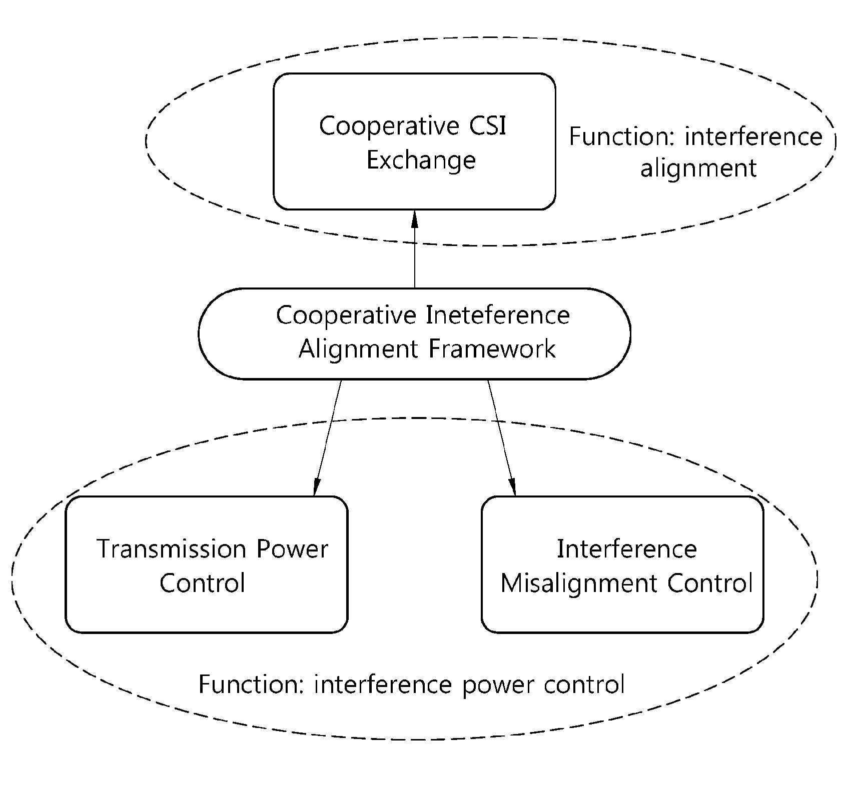
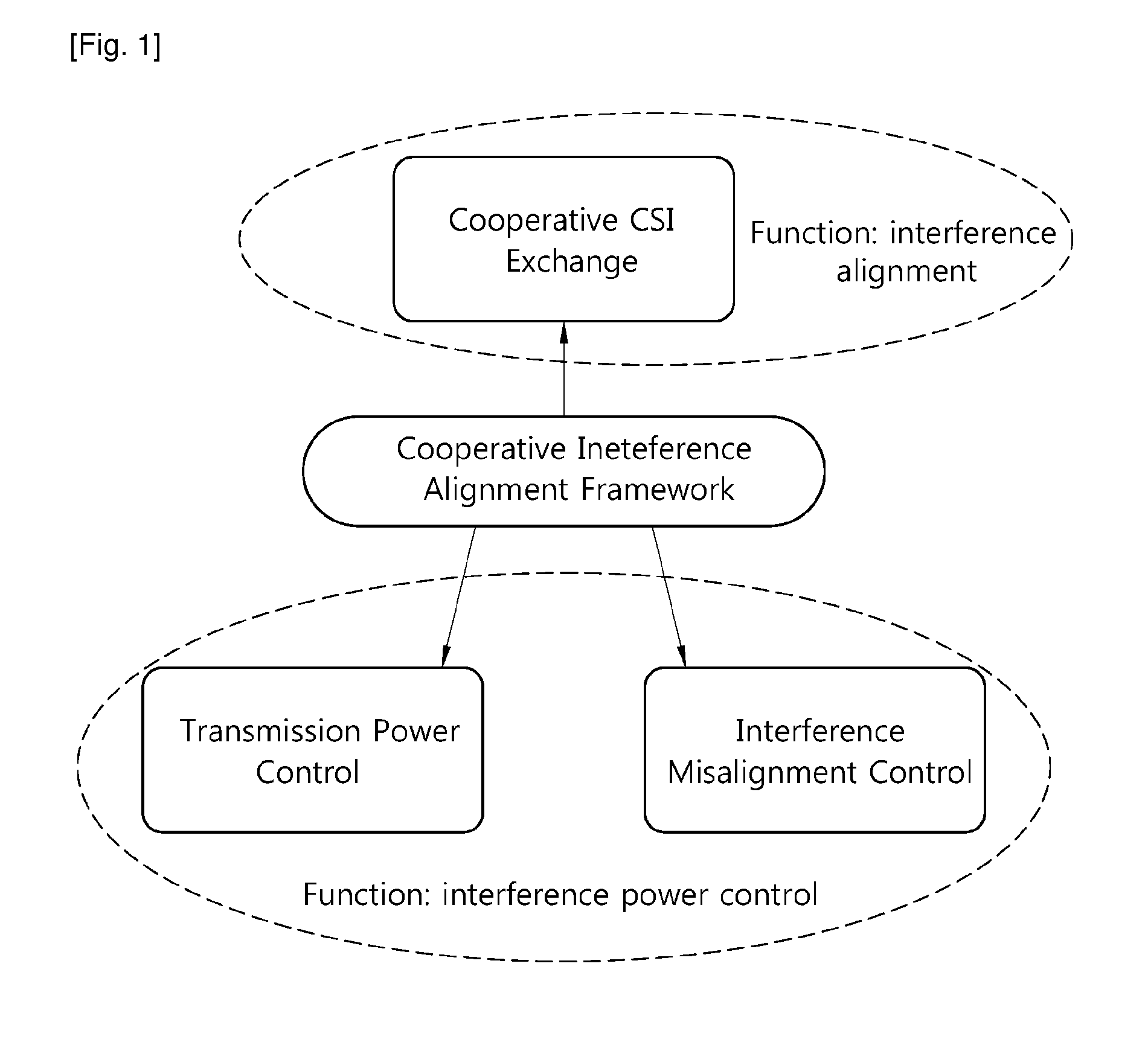
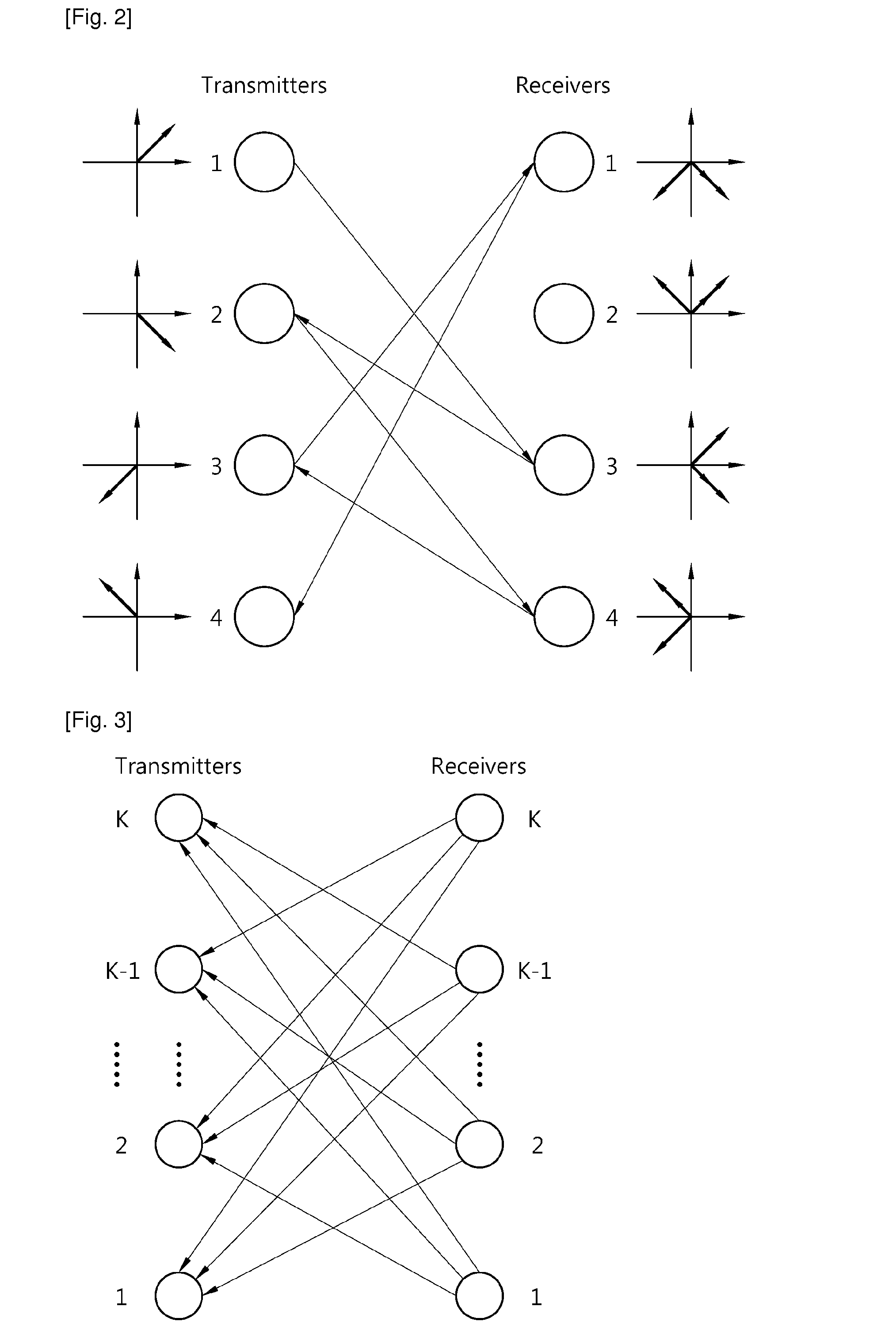

Image

  • Method for interference alignment in wireless network
  • Method for interference alignment in wireless network
  • Method for interference alignment in wireless network

Examples


case 1

A. M≦N and D*≦N

[0209]For this case, there are extra DoF at each receiver such that achieving D* does not require IA(interference alignment). Also there is no need of CSIT for achieving D*. Although using any random precoders at transmitter, all operation to cancel interferences can be done at receiver side.

case 2

B. M≦N and D*>N

[0210]If there exists achievable DoF vector d=[d1,d2,d3] to satisfy one among the following two constraints, then the interference coordination method explained below can achieve the optimal integer DoF(D*) and reduction of CSI error amplication.

[Contraints 1]

2d1+3d2≦2N when d1<d2 and d3=d2   1.

3d1+2d3≦2N when d1=d2 and d1<d3.   2.

[0211]Under either of the above two constraints, D* can be achieved by the following interference coordination method based on interference alignment. Above constraints can be derived intuitively. Let consider following parameter,

λ=d1+d2+d3−N

, where it is the number of overlap dimension means that at least λ beams should be aligned at each receiver. CSI error amplification issue comes from coupling condition of IA. If λ=di, all beams at each transmitter are coupled with other beams from other 2 transmitters, which results in the requirement of all cross link CSIT at all transmitters. However, if 2λ≦d2, i.e. 2d1+3d2≦2N, when d12, d3=d...

case 3

C. M>N and D*

[0216]For this case, there are extra DoF at each transmitter such that achieving D*. Differently case 1, this case require CSIT. By using reciprocity, feedback overhead can be efficiently reduced. We propose interference coordination method 2 comprising below steps.

[0217]1. Step 1: Each receiver determines receiver beamformer Ui first ramdomly or maximizing desired channel SINR.

[0218]2. Step 2: Each receiver feeds back UiHHi,k, k≠i to corresponding transmitters.

[0219]3. Step 3:

vim=vm[∑k=1,k≠i3PdiHk,iHUkUkHHk,i],m=1,…di

where vm[A] is the eigenvector corresponding to the dth smallest eigenvalue of A. In the proposed method each receiver feeds back diM non-zero coefficient to 2 transmitters. Total feedback overhead for the proposed algorithm is 6D*M.


PUM


Abstract

A method for interference alignment in wireless network having 3 transmitters and 3 receivers which are equipped with M antennas is provided. The method comprising: transmitting, performed by each of the 3 transmitters, a pilot signal known to the 3 receivers; estimating, performed by each of the 3 receivers, each channel from transmitter; transmitting, performed by each of the 3 receivers, feedback information to target transmitter; and determining, performed by transmitter 2 and transmitter 3, a precoding vector; wherein a degree of freedom(DoF) of a transmitter 1 is (M / 2−α), a DoF of the transmitter 2 or the transmitter 3 is M / 2.

Description

TECHNICAL FIELD[0001]The present invention relates to wireless communication, and more particularly, to a method for interference alignment in wireless network.BACKGROUND ART[0002]In a wireless network with multiple interfering links, interference alignment (IA) is used. IA is a transmission scheme achieving linear sum capacity scaling with the number of data links, at high SNR. With IA, each transmitter designs the precoder to align the interference on the subspace of allowable interference dimension over the time, frequency or space dimension, where the dimension of interference at each receiver is smaller than the total number of interferers. Therefore, each receiver simply cancels interferers and acquires interference-free desired signal space using zero-forcing (ZF) receive filter.[0003]Most of conventional research on IA is considered to achieve the maximum gain of IA using the infinite selectivity over symbol extensions, which is unrealistic in practical wireless networks. Th...

Claims


Application Information

Patent Timeline
IPC IPC(8): H04B15/00
CPCH04B7/0417H04B7/0626H04L25/03343H04B7/0617H04W52/04H04L1/0029H04L2025/03808H04B7/0658H04L25/0224H04B7/0639H04W52/243
Inventor SEO, HAN BYULHUANG, KAIBINROH, SOON SUKCHO, SUNG YOONCHAE, HYUK JINKIM, BYOUNG HOONKIM, DONG KU
Owner LG ELECTRONICS INC
Learn More