
Releasable pack for parachuting when carrying equipment

Active Publication Date: 2012-11-22
5 11 INC
View PDF2 Cites 9 Cited by
  • Summary
  • Abstract
  • Description
  • Claims
  • Application Information

AI Technical Summary

Benefits of technology

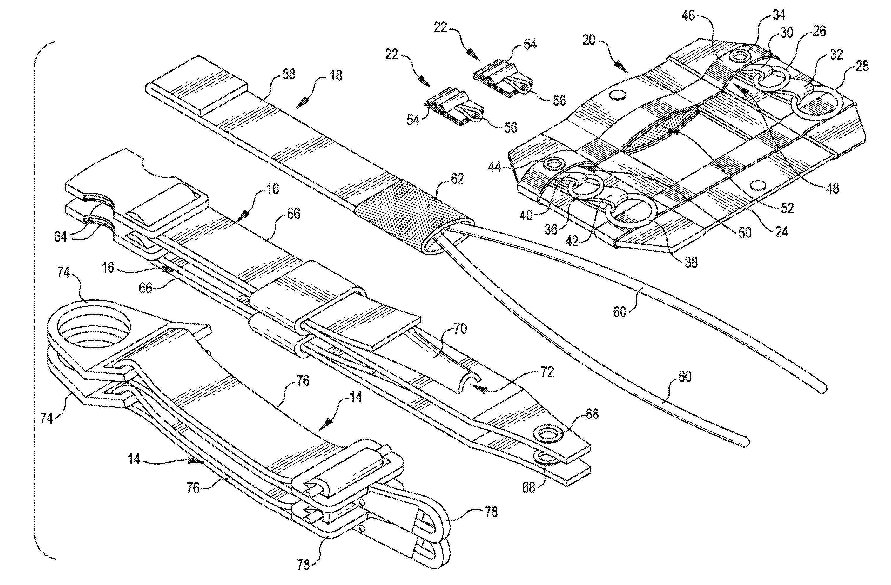
[0006]Improved separating mechanisms for releasing an equipment bag from a parachutist are disclosed. In many embodiments, a separating mechanism includes a removable locking soft loop(s) that can be easily replaced when the locking soft loop(s) becomes torn, frayed, or otherwise unfit for continued use. In many embodiments, a separating mechanism includes a ring release system instead of webbing and / or cord loops. Such a ring release system is stronger than a loop release system and has significantly lower chance of locking up and failing to release the equipment bag. In many embodiments, the equipment bag is contoured in an aerodynamic shape (e.g., an inverted pyramid), thereby making it easier for the parachutist to maintain stability during free fall. And in many embodiments, the equipment bag includes an integral cinch cord(s) to better secure items inside the equipment bag as well as to constrain loose portions of the equipment bag.
[0010]In many embodiments, the removable locking soft loop assembly is not fixedly attached to the base assembly. In many embodiments, the base assembly is configured to retain the removable locking soft loop assembly after the attachment ring is released. For example, the locking soft loop assembly can be retained between the aperture and the base member after the attachment ring is released. The removable locking soft loop assembly can include a removal tab coupled with the locking soft loop base. The removal tab provides a gripping surface by which a user can pull the removable locking soft loop assembly free from the base assembly to facilitate replacement of the removable locking soft loop assembly.
[0015]In many embodiments, the removable locking soft loop assemblies are not fixedly attached to the base assembly. And in many embodiments, the base assembly is configured to retain the removable locking soft loop assemblies after the attachment rings are released. For example, the locking soft loop assemblies can be retained between the respective aperture and the base member after the attachment rings are released. Each of the removable locking soft loop assemblies can include a removal tab coupled with the locking soft loop base. The removal tab provides a gripping surface by which a user can pull the removable locking soft loop assembly free from the base assembly to facilitate replacement of the removable locking soft loop assembly.

Problems solved by technology

Over time, however, the locking soft loops begin to tear and / or fray such that extensive repair or replacement of the equipment bag is required.
The additional release loops may also deteriorate over time from, for example, overuse, heavy weight, and dry weather, until the additional release loops lock up, thereby inhibiting proper release of the equipment bag.

Method used


Image

  • Releasable pack for parachuting when carrying equipment
  • Releasable pack for parachuting when carrying equipment
  • Releasable pack for parachuting when carrying equipment

Examples


Embodiment Construction

[0026]In the following description, various embodiments of the present invention will be described. For purposes of explanation, specific configurations and details are set forth in order to provide a thorough understanding of the embodiments. However, it will also be apparent to one skilled in the art that the present invention may be practiced without the specific details. Furthermore, well-known features may be omitted or simplified in order not to obscure the embodiment being described.

[0027]Separating Mechanism

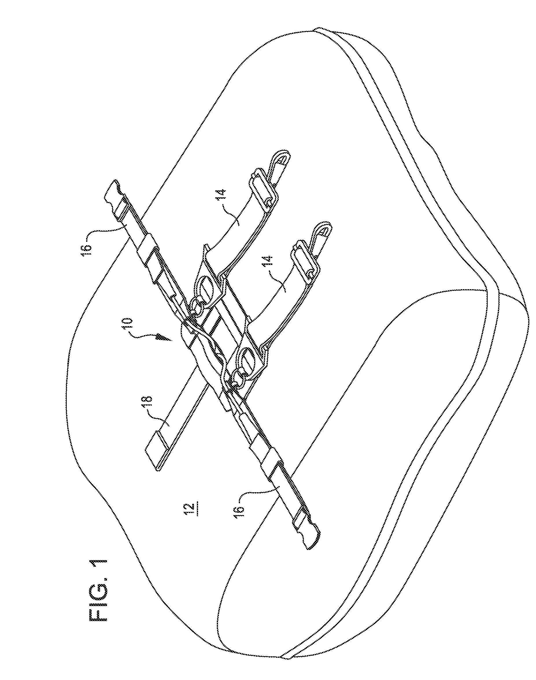
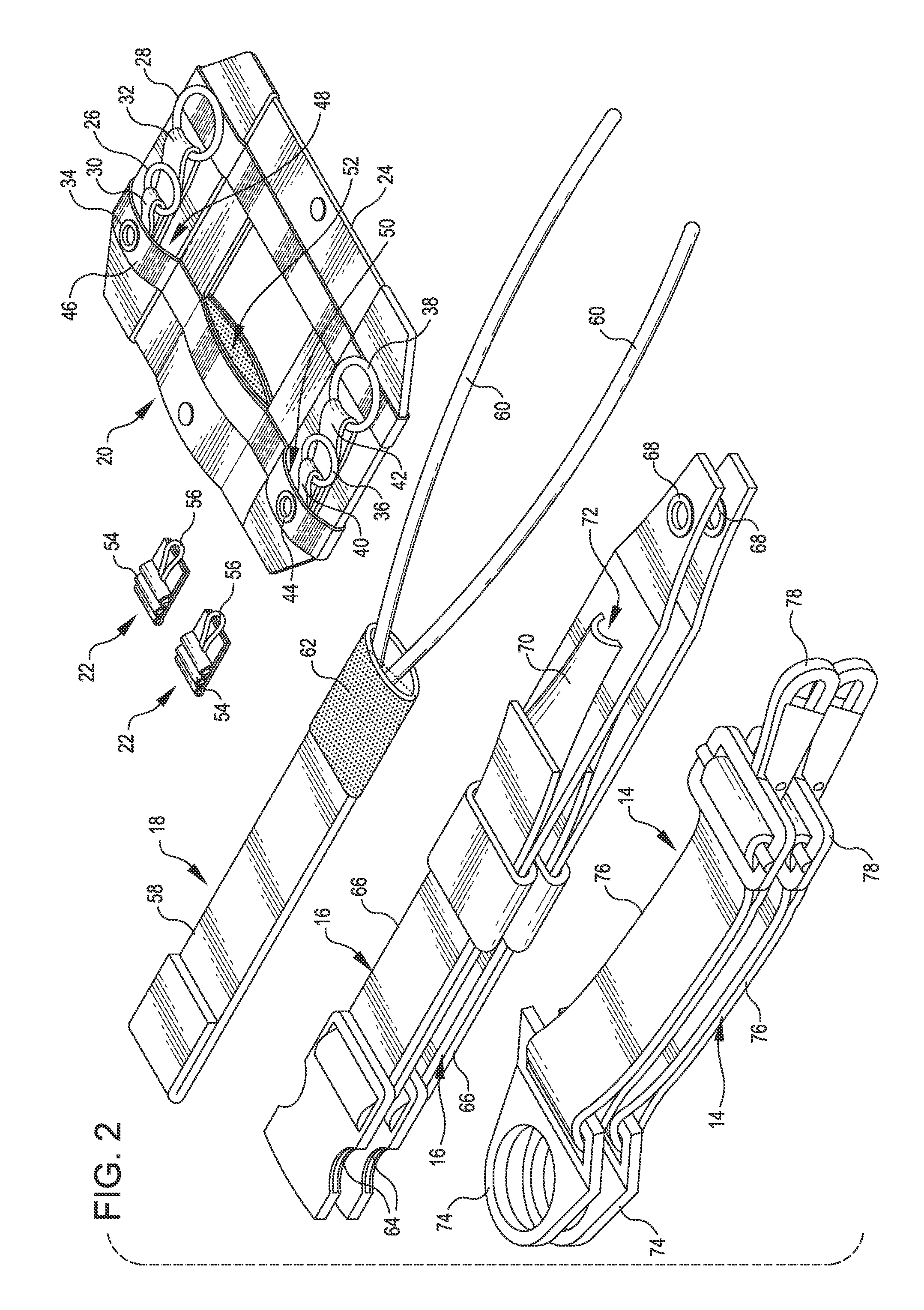
[0028]Referring now to the drawings, in which like reference numerals represent like parts throughout the several views, FIG. 1 shows a separating mechanism 10 attached to an equipment bag 12 for releasing the equipment bag 12 from a parachutist while parachuting, in accordance with many embodiments. Two attach straps 14 and two leg straps 16 are shown coupled with the equipment bag 12 via the separating mechanism 10. The separating mechanism 10 includes a release member ...


PUM


Abstract

A separating mechanism for releasing an equipment bag. The mechanism includes a base assembly, a removable soft loop assembly, an attachment ring, and a retention member. The base assembly includes a base member, an aperture, and one or more base assembly rings. The soft loop assembly includes a soft loop base and a soft loop. The soft loop is inserted through the aperture and a first of the base assembly rings. The soft loop base is configured to not be pulled through the aperture. A last of the base assembly rings is inserted through the attachment ring. The retention member is inserted through the soft loop to restrain the first base assembly ring. The base assembly rings are sequentially engaged to couple the attachment ring with the base member. The retention member is pulled out of the soft loop to release the base assembly rings thereby releasing the attachment ring.

Description

CROSS-REFERENCES TO RELATED APPLICATIONS[0001]This application claims the benefit of U.S. Provisional Application No. 61 / 487,810, entitled “RELEASABLE PACK FOR PARACHUTING WHEN CARRYING EQUIPMENT,” filed May 19, 2011, the entire disclosure of which is hereby incorporated herein by reference.BACKGROUND[0002]The present invention relates to a separating mechanism for releasing an equipment bag while parachuting. For example, a paratrooper can use the equipment bag to carry weapons, ammunition, and assorted equipment. The added weight associated with the equipment bag makes it advantageous to release the equipment bag prior to the parachutist landing so as to avoid subjecting the parachutist to increased impact forces, thereby helping to reduce possible injury.[0003]Many existing equipment bags are coupled with the parachutist by way of a separating mechanism that allows the equipment bag to be repeatedly coupled with and decoupled from the parachutist. Existing separating mechanisms o...

Claims


Application Information

Patent Timeline
IPC IPC(8): A44B11/26
CPCB64D17/46Y10T24/3423B64D17/38B64D17/52
Inventor BERGE, MICHAEL SCOTT
Owner 5 11 INC
Learn More