Support pedestal assembly including a stabilizing collar for stabilizing a support structure

a support pedestal and stabilizing collar technology, applied in the field of support structures, can solve the problems of limited safe obtainable height insufficient structural and inability to safely utilize the support structure, so as to improve the stability of the structure, increase the center of gravity of the support pedestal, and ensure the stability of the support structure.

Inactive Publication Date: 2012-11-22
UNITED CONSTR PROD LLC
View PDF45 Cites 29 Cited by
  • Summary
  • Abstract
  • Description
  • Claims
  • Application Information

AI Technical Summary

Benefits of technology

[0010]Another problem associated with some support structures for elevated surfaces is that the safely obtainable height of the support pedestals is limited due to the increasing instability of the support pedestals as the height of the pedestals, and hence the center of gravity of the pedestals, is increased. The increased height of the center of gravity further compounds the problems associated with disruptive vibrations of the underlying surface.
[0011]It is therefore an objective to provide a support structure for an elevated surface, where the support structure has improved structural stability. It is also an objective to provide a support structure that can enable the safe construction of an elevated surface having an increased height above the fixed surface as compared to existing support structures, particularly in areas that are prone to disruptive vibrations.

Problems solved by technology

One problem that is associated with some support structures for elevated surfaces is that the support structures do not provide adequate structural stability in certain unstable environments.
As a result, the support structures cannot be safely utilized in certain seismically active geographic areas, high wind areas or other locations that may be subject to disruptive vibrations of the fixed surface.
Another problem associated with some support structures for elevated surfaces is that the safely obtainable height of the support pedestals is limited due to the increasing instability of the support pedestals as the height of the pedestals, and hence the center of gravity of the pedestals, is increased.
The increased height of the center of gravity further compounds the problems associated with disruptive vibrations of the underlying surface.

Method used


Image

  • Support pedestal assembly including a stabilizing collar for stabilizing a support structure
  • Support pedestal assembly including a stabilizing collar for stabilizing a support structure
  • Support pedestal assembly including a stabilizing collar for stabilizing a support structure

Examples


Embodiment Construction

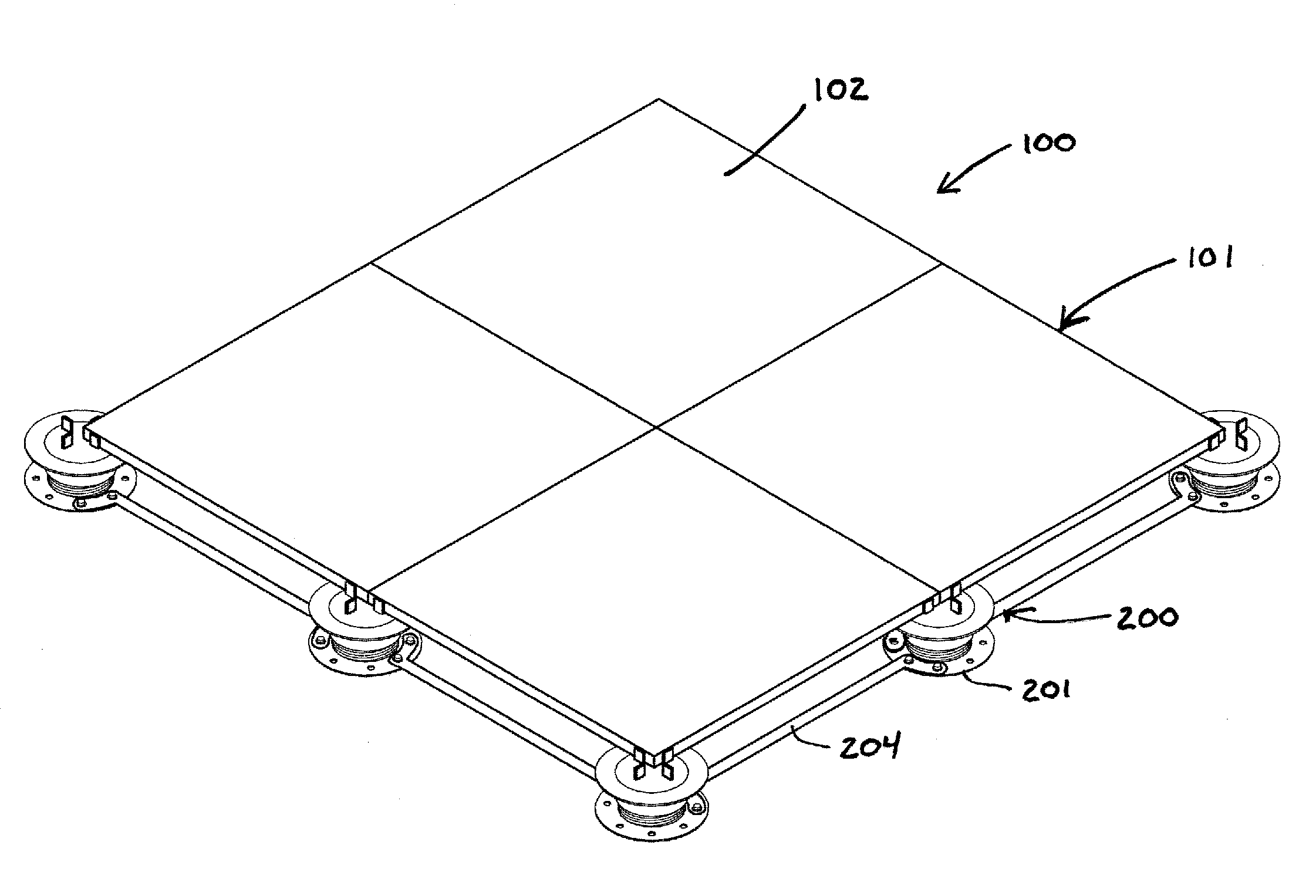
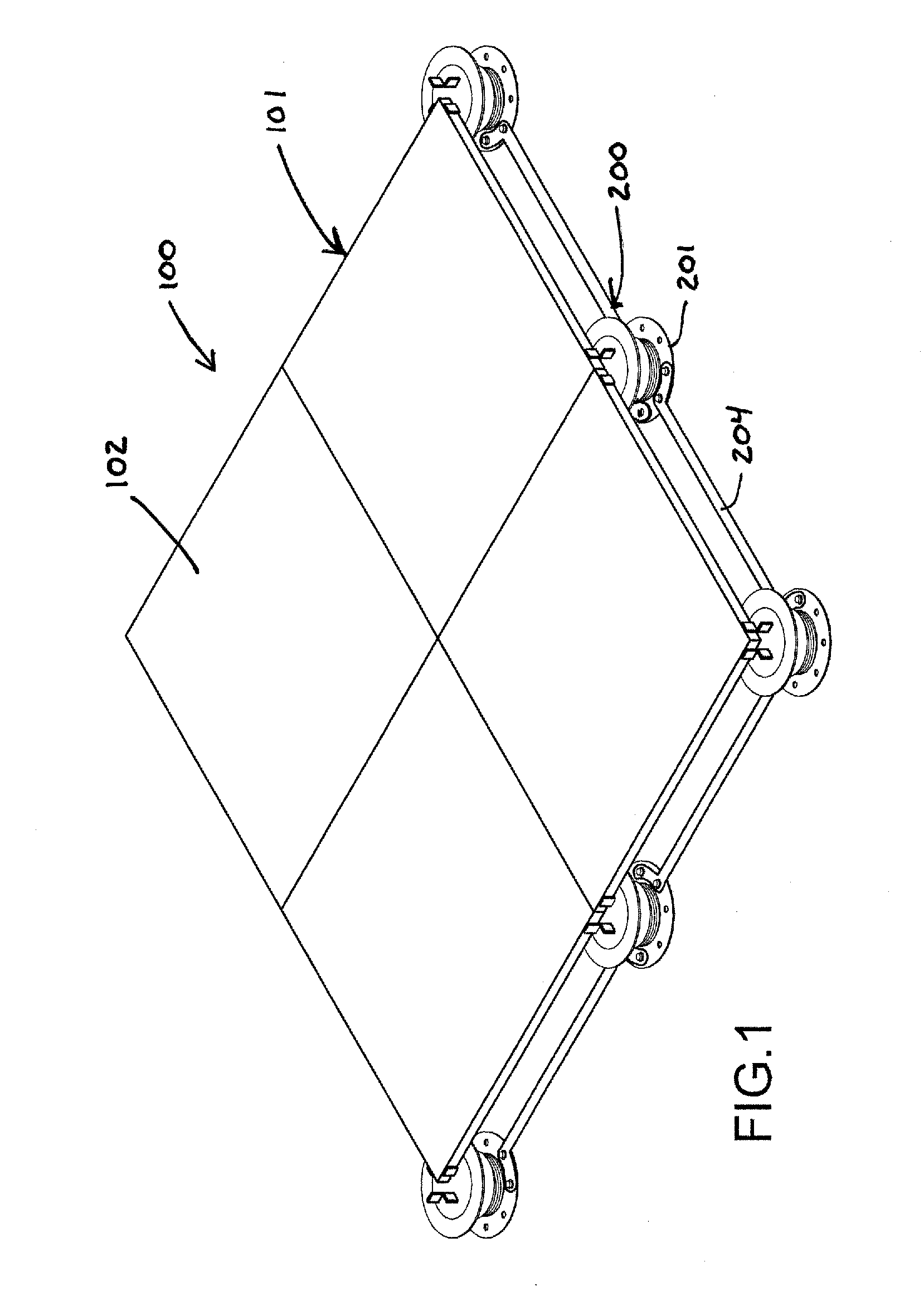
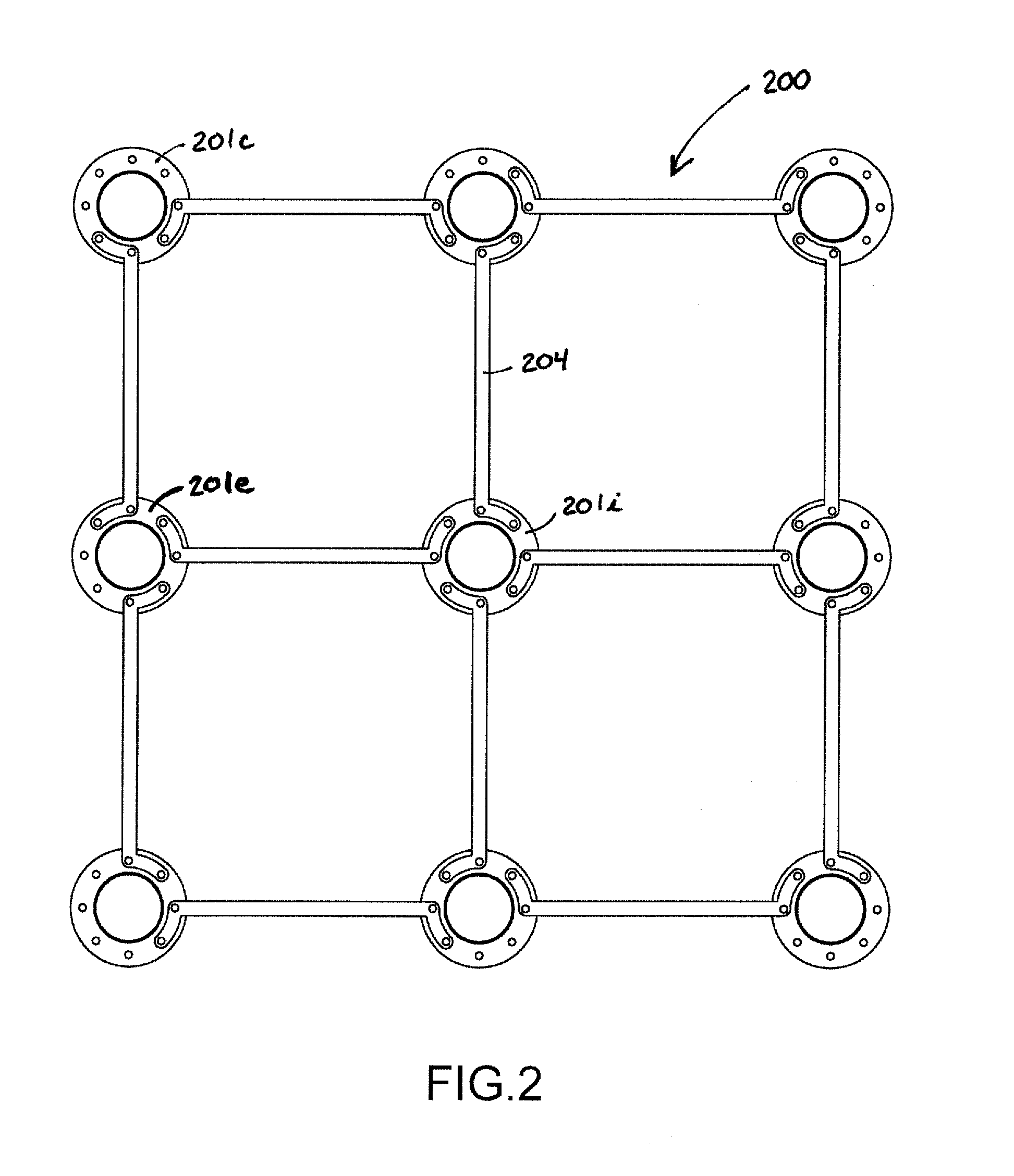
[0041]FIG. 1 illustrates a portion of an elevated building surface assembly 100 that includes a building surface 101 formed from a plurality of surface tiles 102. The surface tiles 102 are elevated above a fixed surface by a support structure 200 comprising a plurality of spaced-apart support pedestals 201 and a plurality of braces 204 interconnecting the support pedestals. The surface tiles 102 can be comprised of virtually any material from which a building surface is constructed. Examples include, but are not limited to, slate tiles, natural stone tiles, composite tiles, concrete tiles (e.g., pavers), wooden deck tiles, particularly hardwood deck tiles, tiles of metal or fiberglass grating, and the like. The support pedestals 201 can be placed in a spaced-apart relationship on fixed surfaces including, but not limited to, rooftops, on-grade (e.g., natural ground), over concrete slabs including cracked concrete slabs, and can be placed within fountains and water features, used for...


PUM


Abstract

A support structure for elevating a building surface above a fixed surface having stability bracing to provide increased stability to the structure. The support structure includes a plurality of support pedestals that are disposed in spaced-apart relation on a fixed surface. A plurality of braces are attached to adjacent support pedestals to interconnect the support pedestals. Interconnecting the support pedestals in such a manner creates a stable support structure that can be utilized in unstable environments, such as seismically active geographic areas. The support pedestals can be adjustable-height support pedestals.

Description

RELATED APPLICATIONS[0001]This application is a continuation-in-part of U.S. patent application Ser. No. 12 / 505,217, filed Jul. 17, 2009, entitled “STABILITY BRACING OF A SUPPORT STRUCTURE FOR ELEVATING A BUILDING STRUCTURE,” and now U.S. Pat. No. 8,181,399, the entire disclosure of which is hereby incorporated by reference in its entirety.BACKGROUND OF THE INVENTION[0002]1. Field of the Invention[0003]This invention relates to the field of support structures for supporting an elevated surface above a fixed surface, such as for elevated floors, decks and walkways.[0004]2. Description of Related Art[0005]Elevated building surfaces such as elevated floors, decks, terraces and walkways are desirable in many environments. One common system for creating such surfaces includes a plurality of surface tiles, such as concrete tiles (pavers), stone tiles or wood tiles, and a plurality of spaced-apart support pedestals upon which the tiles are placed to be supported above a fixed surface. For ...

Claims


Application Information

Patent Timeline
Patent Type & Authority Applications(United States)
IPC IPC(8): E04B5/43E04B5/00
CPCE04D11/007E04G21/14E04F15/0247E04F15/02183E04F2015/02127
Inventor KNIGHT, III, STEPHEN J.KUGLER, WILLIAM E.
Owner UNITED CONSTR PROD LLC
Why Eureka
Try Eureka