Angular velocity sensor

Inactive Publication Date: 2012-11-22
SAMSUNG ELECTRO MECHANICS CO LTD
View PDF2 Cites 16 Cited by
  • Summary
  • Abstract
  • Description
  • Claims
  • Application Information

AI Technical Summary

Benefits of technology

[0012]An aspect of the present invention provides an angular velocity sensor which improves sensitivity characteristics by correcting resonance frequencies in a

Problems solved by technology

However, the resonance frequency shows a tendency to move out of a designed value due to manufacturing distribution, environmental change, and time lapse of the angular velocit

Method used


Image

  • Angular velocity sensor
  • Angular velocity sensor
  • Angular velocity sensor

Examples


Embodiment Construction

[0048]Embodiments of the present invention will now be described in detail with reference to the accompanying drawings. However, it should be noted that the spirit of the present invention is not limited to the embodiments set forth herein and those skilled in the art and understanding the present invention could easily accomplish retrogressive inventions or other embodiments included in the spirit of the present invention by the addition, modification, and removal of components within the same spirit, but those are to be construed as being included in the spirit of the present invention.

[0049]Further, like reference numerals will be used to designate like components having similar functions throughout the drawings within the scope of the present invention.

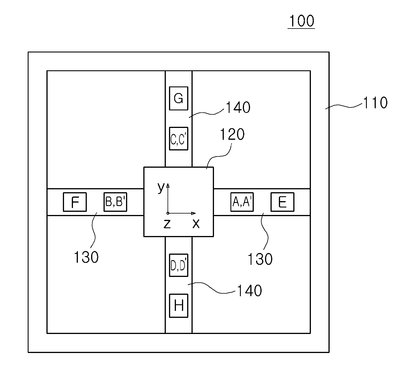
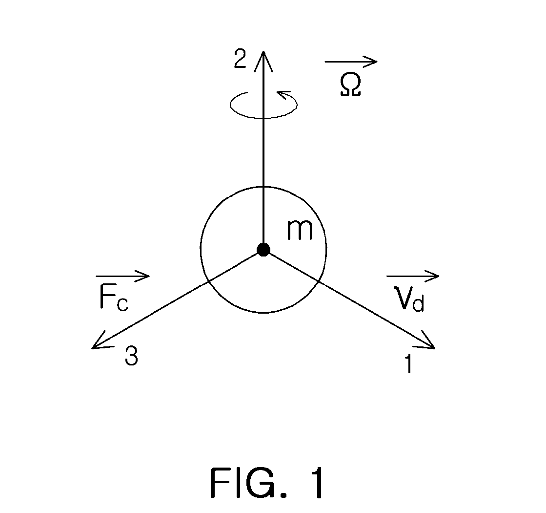
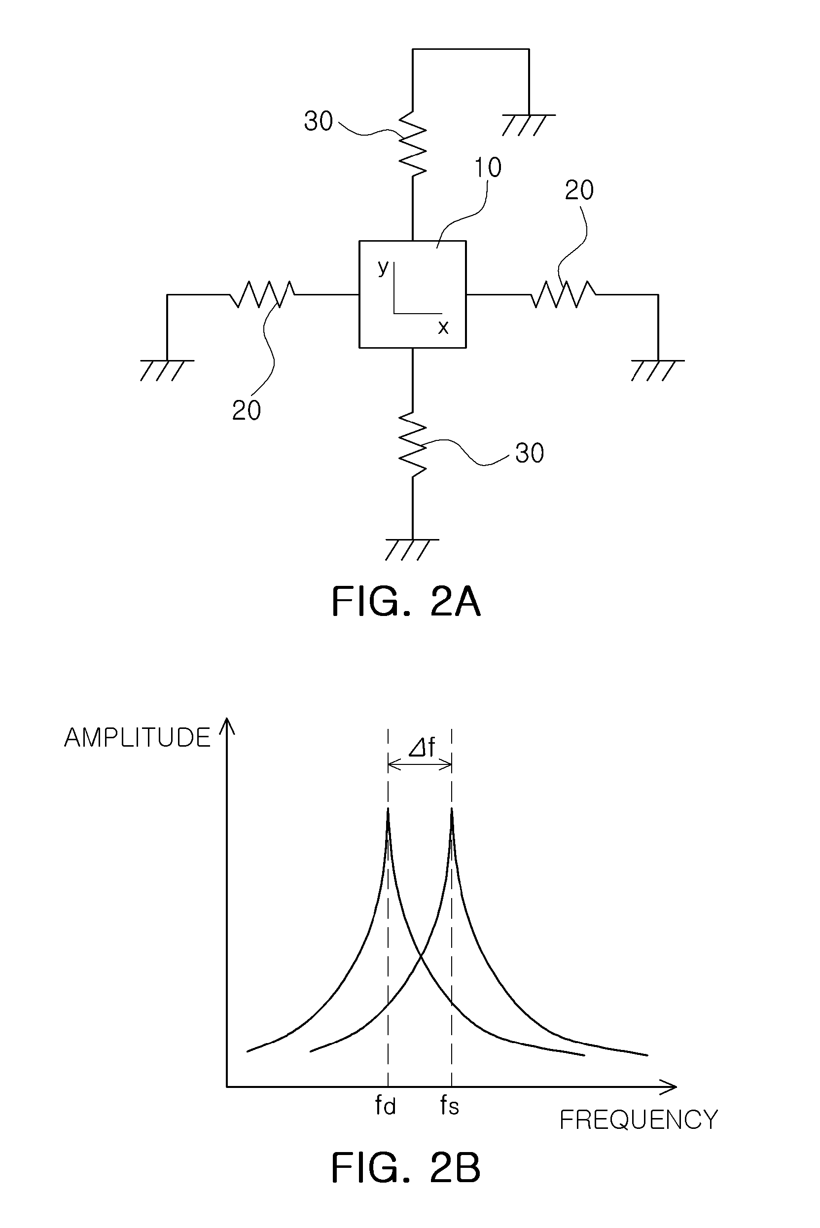
[0050]FIG. 1 is a conceptual diagram showing an operational principle of an angular velocity sensor according to an embodiment of the present invention and FIGS. 2A and 2B are basic conceptual diagrams for explaining a mechanical ...


PUM


Abstract

There is provided an angular velocity sensor, including: a flexible part connecting a fixing part to an oscillation unit; a driving unit formed on the flexible part or the oscillation unit to oscillate the oscillation unit; a sensing unit formed on the flexible part or the oscillation unit to sense a displacement of the oscillation unit according to an angular velocity input; a control piezoelectric element formed on the flexible part to control rigidity of a motion of the oscillation unit; and an impedance element electrically connected to the control piezoelectric element to apply impedance to the control piezoelectric element.

Description

CROSS-REFERENCE TO RELATED APPLICATIONS[0001]This application claims the priority of Korean Patent Application No. 10-2011-0048032 filed on May 20, 2011, in the Korean Intellectual Property Office, the disclosure of which is incorporated herein by reference.BACKGROUND OF THE INVENTION[0002]1. Field of the Invention[0003]The present invention relates to an angular velocity sensor, and more particularly, to an angular velocity sensor capable of improving sensitivity characteristics by controlling resonance frequencies in a driving mode and a sensing mode.[0004]2. Description of the Related Art[0005]Micro Electro-Mechanical Systems (MEMS) are a product of technology for manufacturing a specific portion of a system to have a delicate shape in a μm unit by using a silicon process, which means an apparatus in which mechanical parts, sensors, actuators, or electronic circuits are integrated on a single silicon substrate.[0006]A representative application for the MEMS technology is a sensor...

Claims


Application Information

Patent Timeline
IPC IPC(8): G01P3/44
CPCG01C19/5755G01C19/56G01P3/44
Inventor KIM, JONG WOONMINYAO, MAOLIWEI, LINJEUNG, WON KYU
Owner SAMSUNG ELECTRO MECHANICS CO LTD
Why Eureka
Try Eureka