
Stackable cleaning bucket

a cleaning bucket and stacking technology, applied in the field of containers, can solve the problems of difficult to keep the bucket clean, accumulate dirt, and be very taxing, and achieve the effect of small cross-section

Active Publication Date: 2012-11-22
THERMTECS
View PDF4 Cites 3 Cited by
  • Summary
  • Abstract
  • Description
  • Claims
  • Application Information

AI Technical Summary

Benefits of technology

[0035]Nevertheless, it is extremely advantageous that these spacers can take any form that continually connects the peripheral surface of the bucket at the small space of the partition panel.
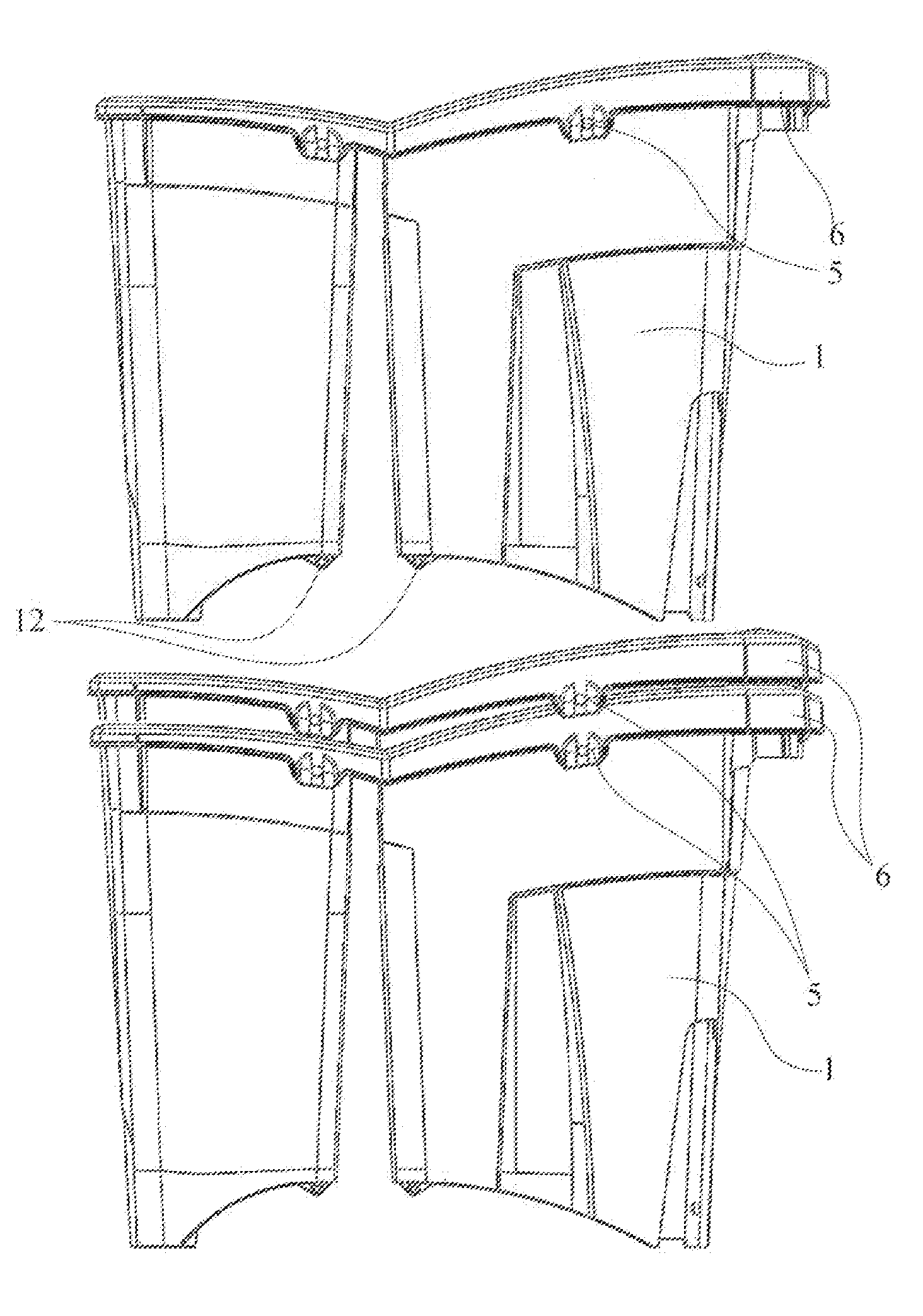
[0036]In the event that during the storage of the cleaning equipment after use, stacking with other identically structured buckets is needed, in order to save space, this will be very easy and quick following the removal of said spacer elements by the operator (or their repositioning in a non-active configuration), thereby permitting stacking on a base bucket (on which no other operation needs to be carried out) of one or more buckets, taking up just a little more vertical space (in general just a little more than the upper reinforcement edge that cleaning buckets usually have) than that of the base bucket.
[0039]Also when there are handles, usually hinged to the top reinforcement edge and with a very small cross-section, the result that can be obtained with the stacking is not compromised, by positioning the handles adjacent to the top edges in a basically horizontal position (if the edge of the bucket is in the same position).

Problems solved by technology

Nevertheless, the difficulties of equipping a bucket with just a single basin and the drawbacks that this accessory involved, have meant that operators in the sector have preferred different solutions.
The difficulty of equipping a bucket with a single basin is mainly related to the insertion and removal of this removable partition, which has to be easily installed (to be pushed forcibly in the guide groove that has to provide the waterproof seal) and has to be equally easy to remove, but which at the same time has to provide the waterproof sealing for each compartment, so as not to pollute the liquid contained in one compartment with the liquid contained in the other, and also to ensure, in the event there is liquid just in one compartment, leakage to the empty adjacent compartment.
The drawbacks that this accessory has involve mainly the difficulty of keeping the bucket clean at the edges inside which the above-mentioned removable partition is housed.
In fact the guide groove, or channel, which is raised with respect to the interior surfaces of the bucket and embedded and therefore sunken into the surface profile of the walls and the bottom of the bucket, because they necessarily have to have a width basically the same as that of the removable partition, is not easily reached for cleaning, so it accumulates dirt especially along the edges.
Later, because of problems connected to the extraction of the molds of the bucket that had a partition, it was necessary to apply a draft angle to the partition.
If by using this well-known method it was possible to easily extract the above-mentioned bucket from the mold, it nevertheless proved to be very taxing because of the amount of material used and the exaggerated dimensions in relation to the stresses that this partition was subjected to.
Even if this configuration fully satisfies user requirements, nevertheless also these solutions have some serious drawbacks.
In fact manufacturers, who have always been careful in reconciling the performance and features of their products with the costs of production and packing, storage, shipping, found themselves having considerable difficulties and additional charges as regards the aspect of storage, packing and shipping, with an increase in the space taken up by these products in the warehouse and considerable expenses for packing and shipping.
Experimental solutions have been tried out to resolve these drawbacks, but with poor and questionable results.
Up until now, therefore, it is well known that a bucket equipped with a central partition costs more than one without this division, not only because of the depreciation cost of the molds used and the cost of the additional material (generally plastic), but also and especially because of the greater space taken up in each phase, especially in the storage, packing and shipping phases.
If the above-mentioned drawbacks acutely affect manufacturers, retailers and also end-users, the problems connected to the use of these buckets are also important.
In fact these drawbacks are particularly felt in cleaning companies that, having to very often use numerous buckets (usually of the same model), find themselves needing a store for equipment, or a warehouse for various types of cleaning instruments, which is not so tidy and overflowing because of the impossibility of being able to stack the buckets with a partition one on top of another.
In fact the buckets, together with any trolleys, represent the majority of the cleaning tools and are more cumbersome and unwieldy than those normally used by cleaning companies.

Method used


Image

  • Stackable cleaning bucket
  • Stackable cleaning bucket
  • Stackable cleaning bucket

Examples


Embodiment Construction

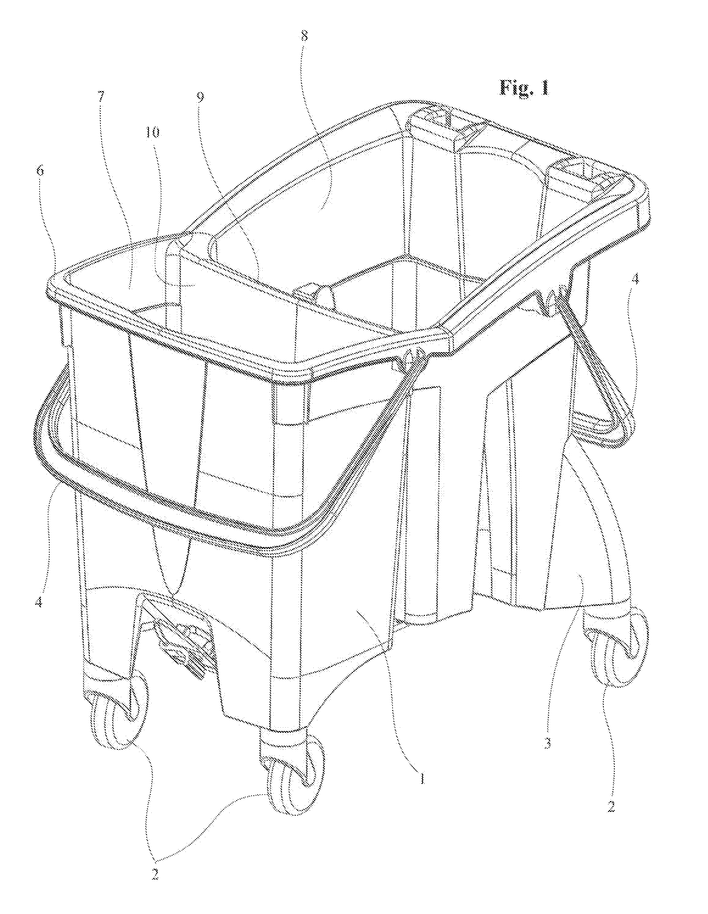
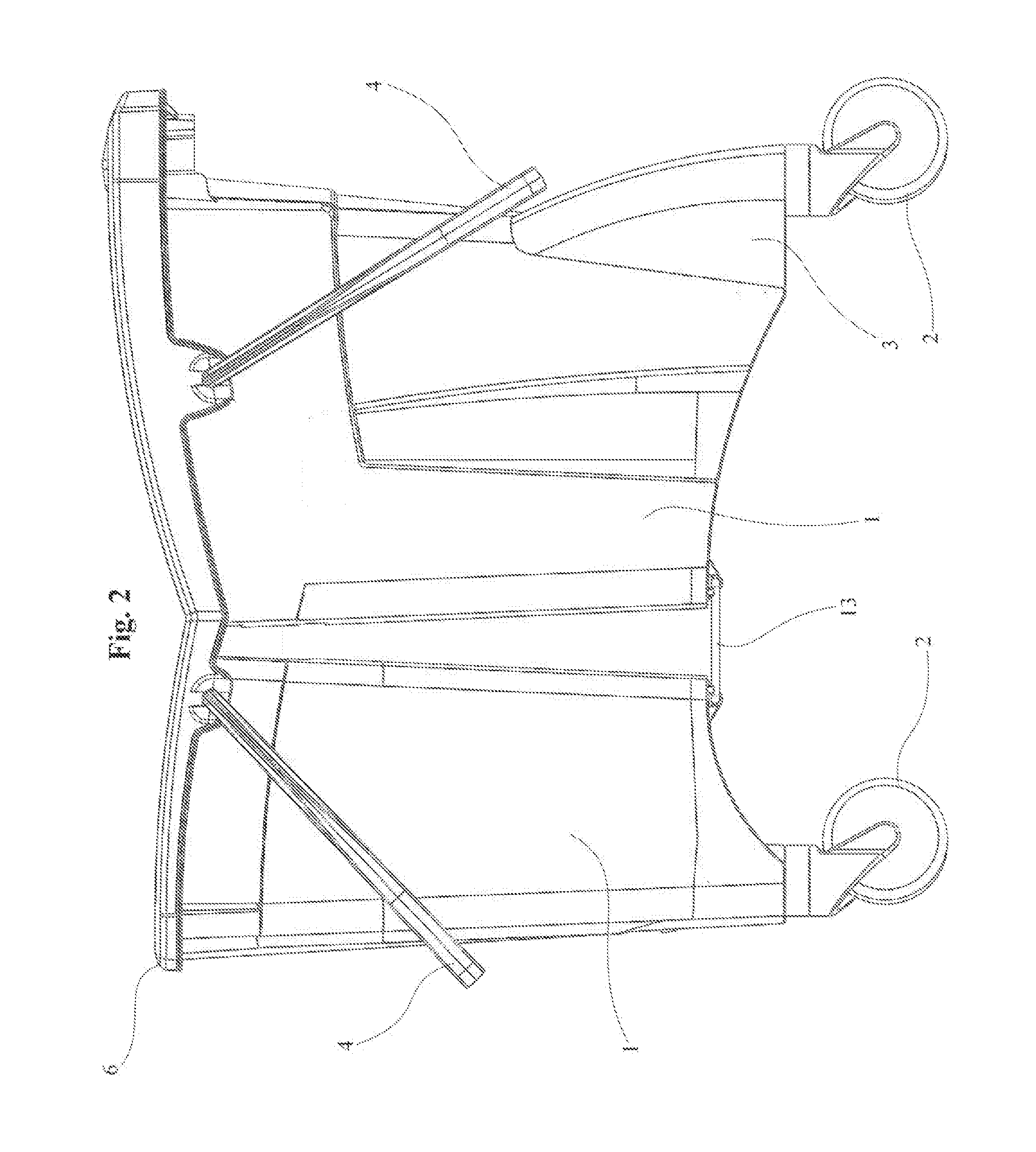
[0050]With reference to the drawings, the cleaning bucket 1 that is shown is a wheeled cleaning bucket, namely one with wheels 2, applied on the bottom to side expansions 3 (or side extensions) which can be removed from the structure of the bucket 1.

[0051]Said bucket has handles 4, whose housings 5 are near the edge 6 of the bucket 1.

[0052]This bucket has two compartments 7, 8 divided by a partition 9.

[0053]This partition 9 is composed of two walls 10, 11 joined only at the top and each part of the side surface of the respective compartment 7, 8.

[0054]At the bottom of the bucket, near the bottom edge of each compartment that faces the adjacent compartment there are the housings 12 into which the spacer elements 13 are inserted.

[0055]In this specific case, the housings 12 are holes with a circular section inside which the C-shaped spacer elements 13 are pushed.

[0056]In order to prevent an accidental uncoupling of the elements 13 from their housings, there is a no-return mechanism 14....


PUM


Abstract

This is a stackable cleaning bucket composed of two adjacent compartments divided by a partition, where the bucket has the merit of being able to be stacked inside a similar bucket practically up to the top edge, and which is equipped with sufficient structural rigidity when in use, with the positioning at the bottom of the two compartments of a spacer element that connects them.

Description

CROSS-REFERENCE TO RELATED APPLICATIONS[0001]This application claims the benefit of PCT Patent Application PCT / IB2011 / 000094, filed on Jan. 19, 2011, and Italian Patent Application PD 2010 A 000010, filed on Jan. 22, 2010, both incorporated herein by reference.STATEMENT REGARDING FEDERALLY SPONSORED RESEARCH AND DEVELOPMENT[0002]Not Applicable.FIELD OF THE INVENTION[0003]This invention relates to containers, and more particularly to a stackable cleaning bucket.DISCUSSION OF RELATED ART[0004]Currently, with the pursuit of greater speed, care and diligence in cleaning operations, the cleaning of a floor has to be done in a single operation instead of the usual two.[0005]To carry out the above-mentioned function, sector operators prefer a bucket that generally has two separate compartments, one for the washing water, usually with some detergent suitable for the conditions you have to work in, and another for the rinse water, because frequent rinses are required.[0006]Alternatively, and...

Claims


Application Information

Patent Timeline
Patent Type & Authority Applications(United States)
IPC IPC(8): B65D21/00
CPCA47L13/58
Inventor ZORZO, RENATO
Owner THERMTECS
Learn More