Heat transfer apparatus

a technology of heat transfer apparatus and heat exchanger, which is applied in the direction of conduction heat transfer modification of electrical apparatus, instruments, and casings of electrical apparatus, which can solve the problems of insufficient or inaccessible convective heat removal in some chassis, cpus, chipsets, and hard drives that consume electrical current and generate heat during operation,

Inactive Publication Date: 2012-11-22
IBM CORP
View PDF81 Cites 42 Cited by
  • Summary
  • Abstract
  • Description
  • Claims
  • Application Information

AI Technical Summary

Problems solved by technology

For example, but not by way of limitation, central processing units (CPUs), chipsets, graphics cards and hard drives consume electrical current and generate heat during operation.
Insufficient heat removal from a heat-generating electrical component may also result in generally unsatisfactory computer perfo

Method used


Image

  • Heat transfer apparatus
  • Heat transfer apparatus
  • Heat transfer apparatus

Examples


Embodiment Construction

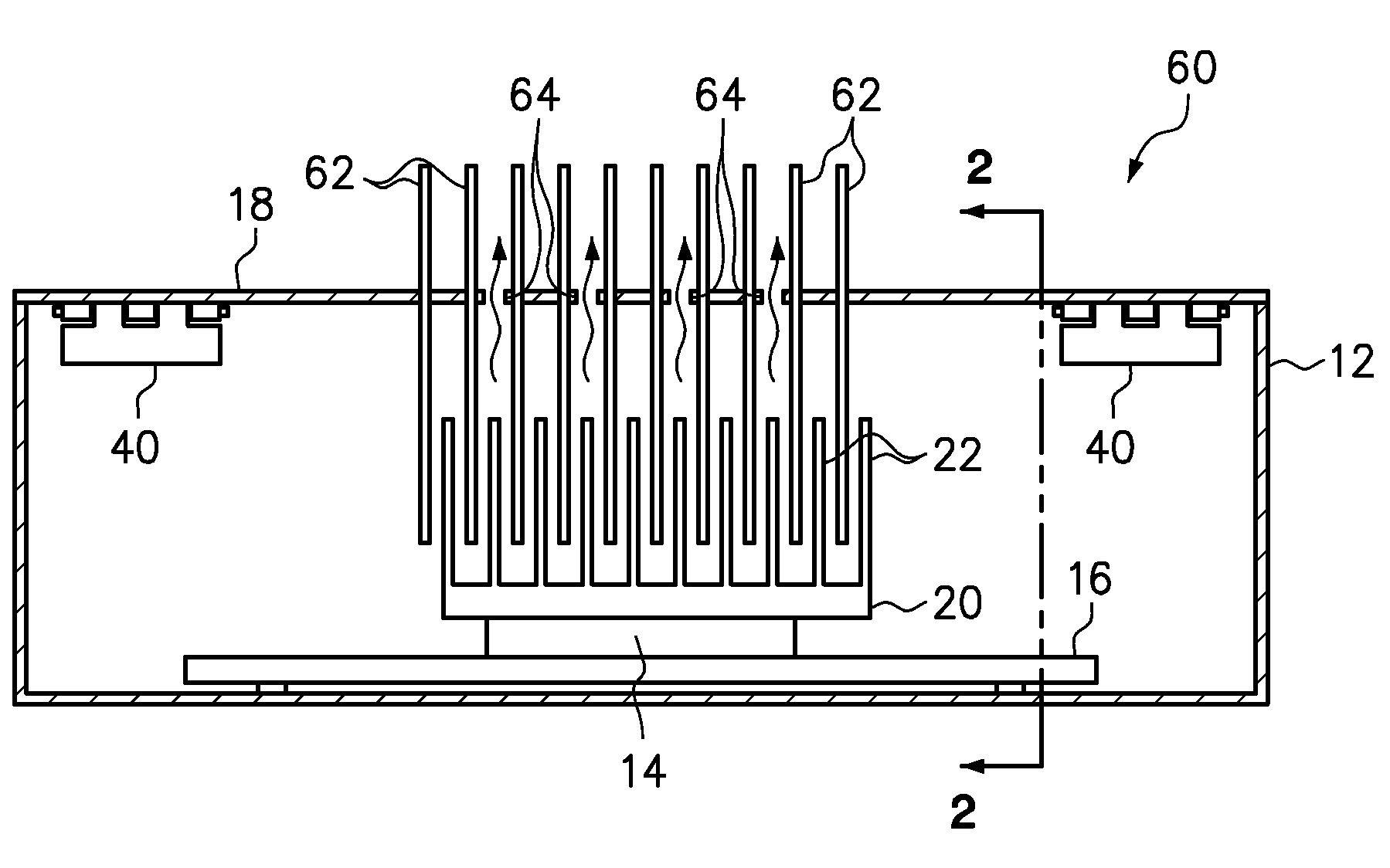
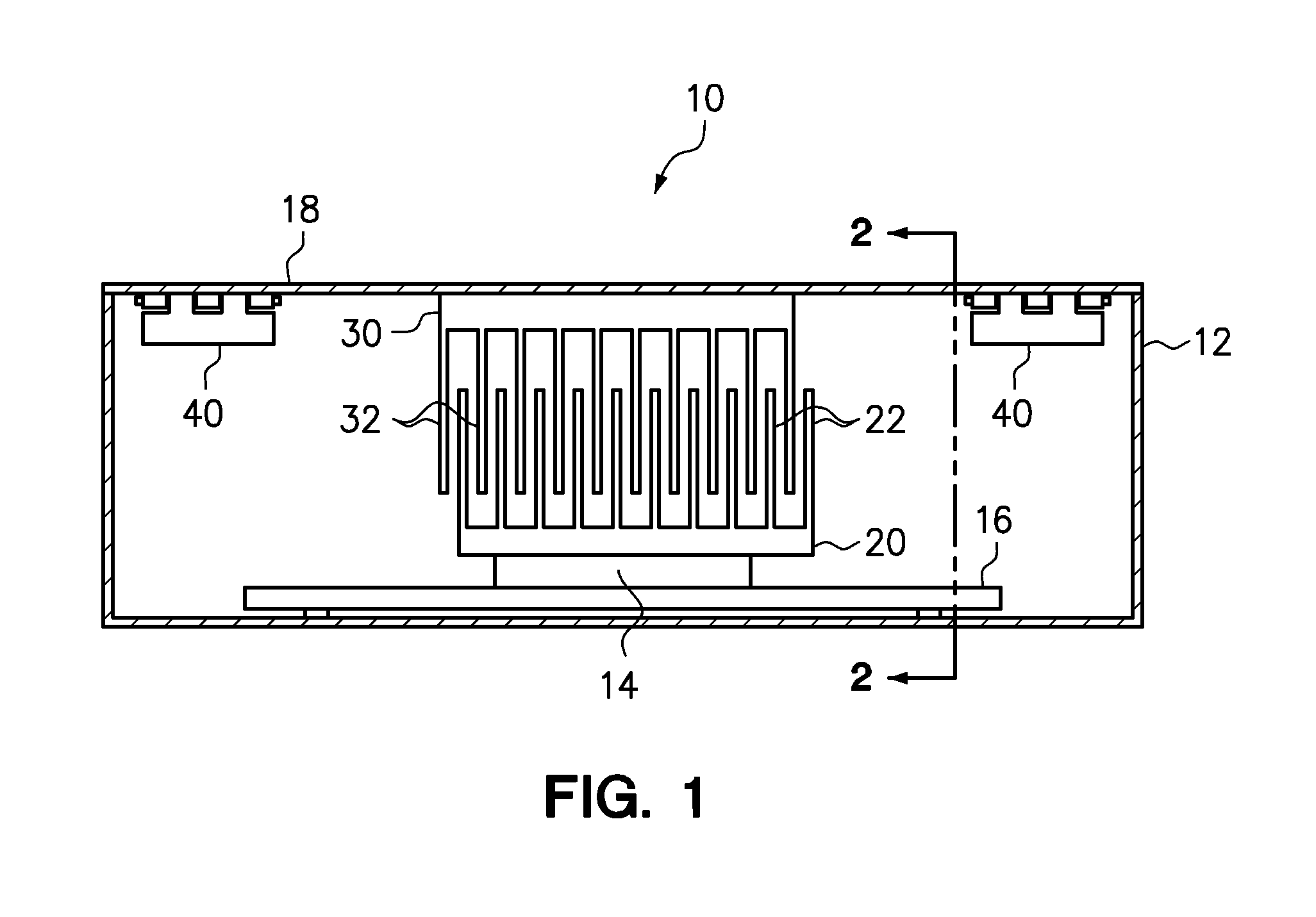
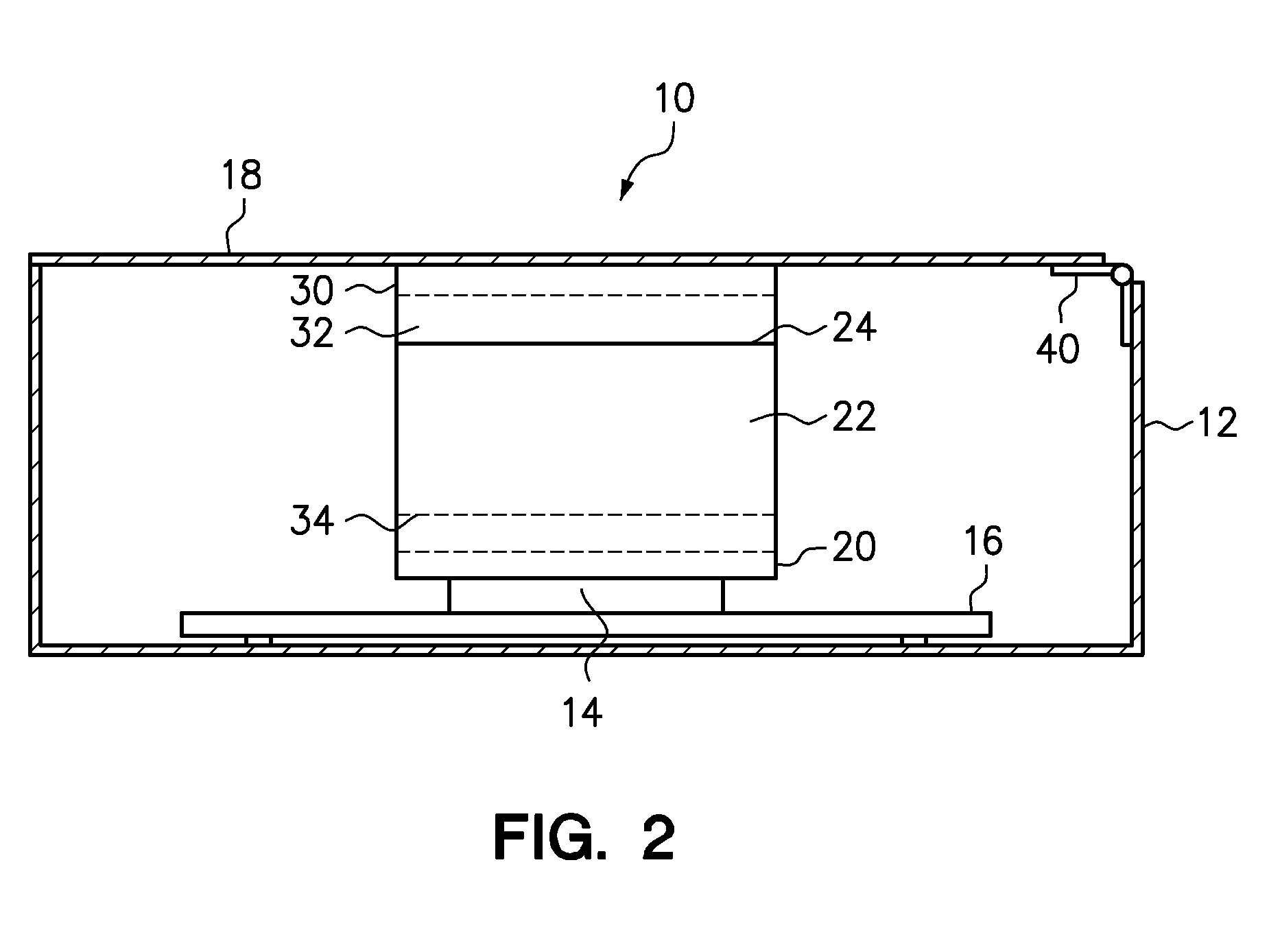
[0014]Various embodiments of the present invention are directed to an apparatus that facilitates passive heat transfer from a first heat sink thermo-conductively coupled to the heat generating component to a second heat sink thermo-conductively coupled to an opposing portion of a chassis. The first heat sink has a plurality of fins, referred to herein as “leader fins,” thermo-conductively coupled to the heat-generating electronic component. The second heat sink also has a plurality of fins, referred to herein as “follower fins,” thermo-conductively coupled to a portion of the computer chassis. The follower fins are interlaced, in an operative position, with the plurality of leader fins to facilitate radiative heat transfer from the plurality of leader fins to the plurality of follower fins. In addition to radiative heat transfer, the apparatus is capable of supporting heat transfer from the first heat sink to the second heat sink through natural convection. Although the apparatus ma...


PUM


Abstract

An apparatus is provided to remove heat from a heat-generating component of a computer, such as a processor. The apparatus comprises a first heat sink having a plurality of leader fins, wherein the first heat sink is thermo-conductively coupled to a heat-generating component that is coupled to a first portion of a chassis; and a second heat sink having a plurality of follower fins, wherein the second heat sink is thermo-conductively coupled to a second portion of the chassis, and wherein the plurality of follower fins are disposed in an interlaced configuration with the plurality of follower fins to promote radiative heat transfer from the leader fins to the follower fins. Optionally, one or more alignment structures may be used to facilitate the relative movement of the first and second chassis portions into an operative position in which the leader and follower fins are in the interlaced configuration. The apparatus may be used to remove heat from a heat-generating component in a closed system with little or no limited air flow.

Description

BACKGROUND[0001]1. Field of the Invention[0002]The present invention relates generally to systems that remove heat generated within computer systems, and more specifically to heat sinks that draw heat away from a heat-generating device such as, for example, a CPU.[0003]2. Background of the Related Art[0004]Computers generally include heat-generating components that consume electrical current and generate heat in an operative mode. For example, but not by way of limitation, central processing units (CPUs), chipsets, graphics cards and hard drives consume electrical current and generate heat during operation. A CPU may comprise thousands or even millions of circuit elements disposed within a square centimeter so that the heat generation density is very high. This heat must be removed from the electrical component in order to maintain performance, prevent unwanted material degradation and to prevent premature failure of the component. Insufficient heat removal from a heat-generating el...

Claims


Application Information

Patent Timeline
IPC IPC(8): H05K7/20
CPCH01L23/367H01L2924/0002H05K7/2039H01L2924/00H05K7/20445
Inventor HERRING, DEAN F.MATTESON, JASON A.WORMSBECHER, PAUL A.
Owner IBM CORP
Why Eureka
Try Eureka