Removable light engine

a light engine and a technology of a light source, applied in the field of light engines, can solve the problems of increased tool and/or equipment, inconvenient implementation, and insufficient heat dissipation, so as to improve heat dissipation, reduce damage or perturbation, and reduce the risk of damage or disturbance

Active Publication Date: 2012-11-22
KONINKLIJKE PHILIPS ELECTRONICS NV
View PDF12 Cites 12 Cited by
  • Summary
  • Abstract
  • Description
  • Claims
  • Application Information

AI Technical Summary

Problems solved by technology

These techniques of attachment needs additional tool and / or equipment, and are therefore not convenient to implement.
Furthermore, the heat dissipation is not optimum due to the presence of intermediate materials between the LED chip, the magnetic element and the frame (electrical conductive and dielectric materials).

Method used


Image

  • Removable light engine
  • Removable light engine
  • Removable light engine

Examples


Embodiment Construction

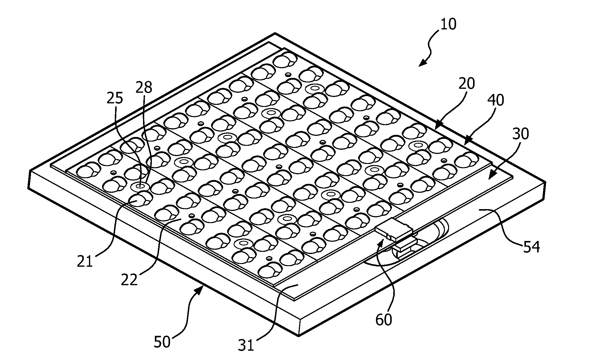
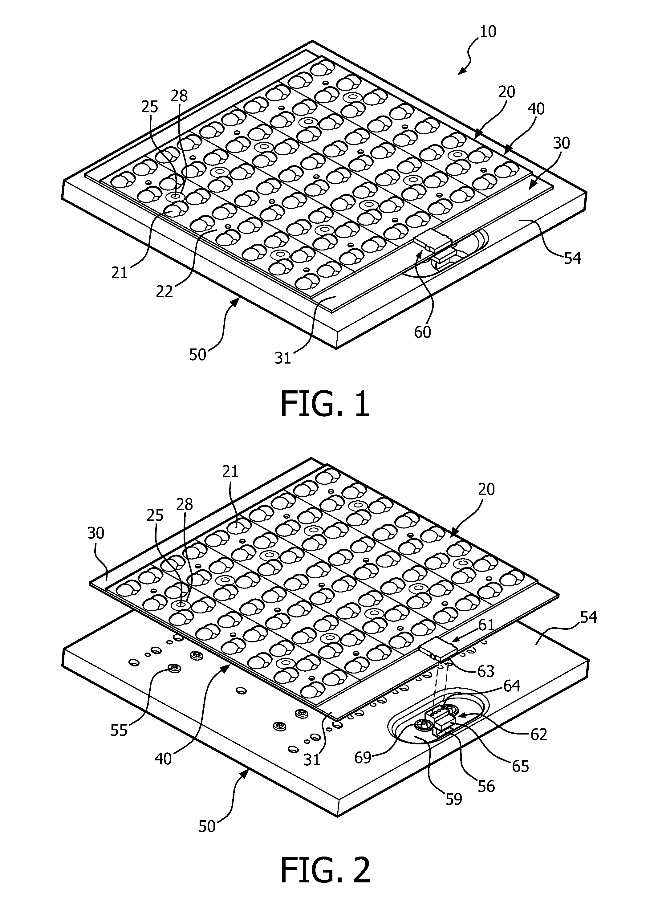
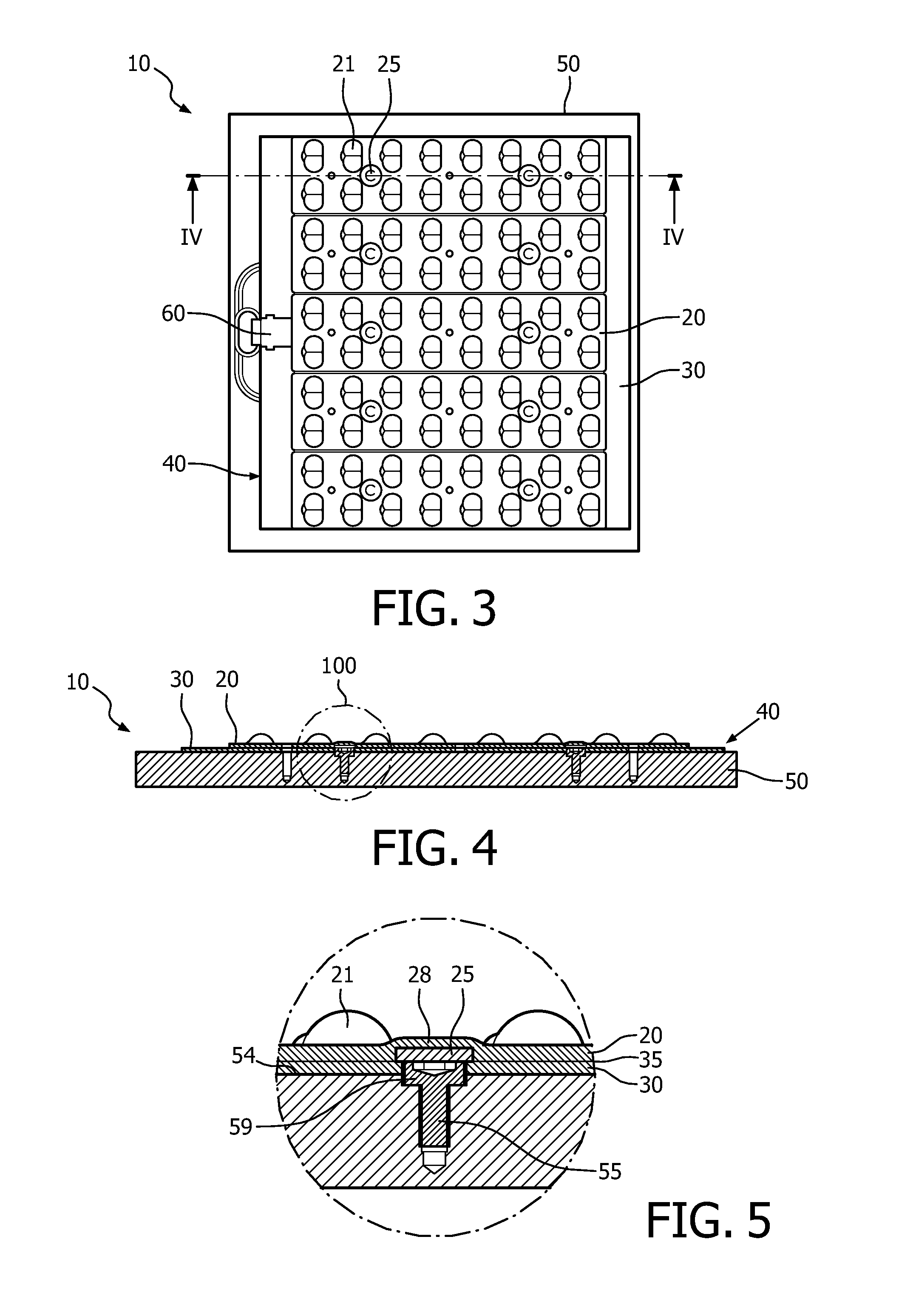
[0045]FIG. 1 through FIG. 6 depicts a particular embodiment of the invention corresponding to a light device 10, comprising a light engine 40 and a support holder 50 bearing the light engine 40. The light engine 40 comprises an optical device 20 and a light-emitting device 30 attached one to the other.

[0046]The light-emitting device 30 comprises, according to this particular embodiment, Light-Emitting Diodes (“LEDs”) as light sources (not shown). The light-emitting device 30 may also comprise a circuit board with a circuitry, and potentially some electronic components, arranged to distribute electrical power, and potentially control signals, to the LEDs. The circuit board may also comprise some electronic components to control, adjust and / or tune signals and / or supply power. The circuit board may be equipped with a first connecting device 61, for example at an end portion 31 of the light-emitting device 30. This first connecting device 61 may be arranged to be connected with a count...


PUM


Abstract

The invention relates to a light engine (40) comprising: a light-emitting device (30) comprising at least one light source; an optical device (20) attached to the light-emitting device (30); and at least one first magnetic element (25) between the light-emitting device (30) and the optical device (20). The invention relates also to a light device (10) comprising: said light engine (40); and a support holder (50) arranged to bear the light engine (40), comprising a magnetic material adapted such that the at least one first magnetic element (25) of the light engine (40) and this magnetic material are magnetically attracted one to the other to magnetically attach the light engine (40) to the support holder (50).

Description

FIELD OF THE INVENTION[0001]The invention relates to a light engine comprising:[0002]a light-emitting device comprising at least one light source;[0003]an optical device attached to the light-emitting device;[0004]The light-emitting device of such a light engine may comprise at least one Light-Emitting Diode (LED) as a light source and a circuit board to carry, supply power to and potentially control the LED(s).[0005]Typically, such a light engine is held in a luminaire by a carrier through which the power may be supplied to the light engine. In the case of LED luminaire, this carrier may be also arranged as a heat dissipater, like a heat sink, which further allows the dissipation of the heat from the LEDs.[0006]The invention relates in particular to the coupling of the light engine to the carrier.BACKGROUND OF THE INVENTION[0007]Different techniques for attaching a light engine to a carrier are known, such as screwing or providing an adhesive layer between the light engine and the ...

Claims


Application Information

Patent Timeline
Patent Type & Authority Applications(United States)
IPC IPC(8): F21V5/04F21V21/00
CPCF21V5/007F21V7/0083F21V17/105F21V29/85F21Y2101/02F21Y2105/001F21V17/005F21V29/004F21Y2105/10F21Y2115/10F21K9/00F21V5/10F21S2/005
Inventor MIGNOT, NICOLASTOTHE, BENOIT GEORGES PAUL
Owner KONINKLIJKE PHILIPS ELECTRONICS NV
Why Eureka
Try Eureka