
Method and device for monitoring control channel in a wireless communication system

a wireless communication system and control channel technology, applied in the field of wireless communication, can solve the problem of not being able to transmit all control channels, and achieve the effect of preventing the increase of overhead of user equipment for detecting control channels and guaranteeing backward compatibility with legacy systems

Inactive Publication Date: 2012-11-22
LG ELECTRONICS INC
View PDF3 Cites 29 Cited by
  • Summary
  • Abstract
  • Description
  • Claims
  • Application Information

AI Technical Summary

Benefits of technology

[0017]An additional control region can be defined to transmit a large amount of control information. Backward compatibility with a legacy system is guaranteed, and an overhead of a user equipment for detecting a control channel can be prevented from increasing.

Problems solved by technology

However, it may be ineffective if the channel structure of the single-carrier system is directly used in the multi-carrier system.
Therefore, it may be not enough to transmit all control channels by using only a region for the conventional control channel.

Method used


Image

  • Method and device for monitoring control channel in a wireless communication system
  • Method and device for monitoring control channel in a wireless communication system
  • Method and device for monitoring control channel in a wireless communication system

Examples


Embodiment Construction

[0031]A user equipment (UE) may be fixed or mobile, and may be referred to as another terminology, such as a mobile station (MS), a mobile terminal (MT), a user terminal (UT), a subscriber station (SS), a wireless device, a personal digital assistant (PDA), a wireless modem, a handheld device, etc.

[0032]A base station (BS) is generally a fixed station that communicates with the UE and may be referred to as another terminology, such as an evolved node-B (eNB), a base transceiver system (BTS), an access point, etc.

[0033]Each BS provides a communication service to a specific geographical region (generally referred to as a cell). The cell can be divided into a plurality of regions (referred to as sectors).

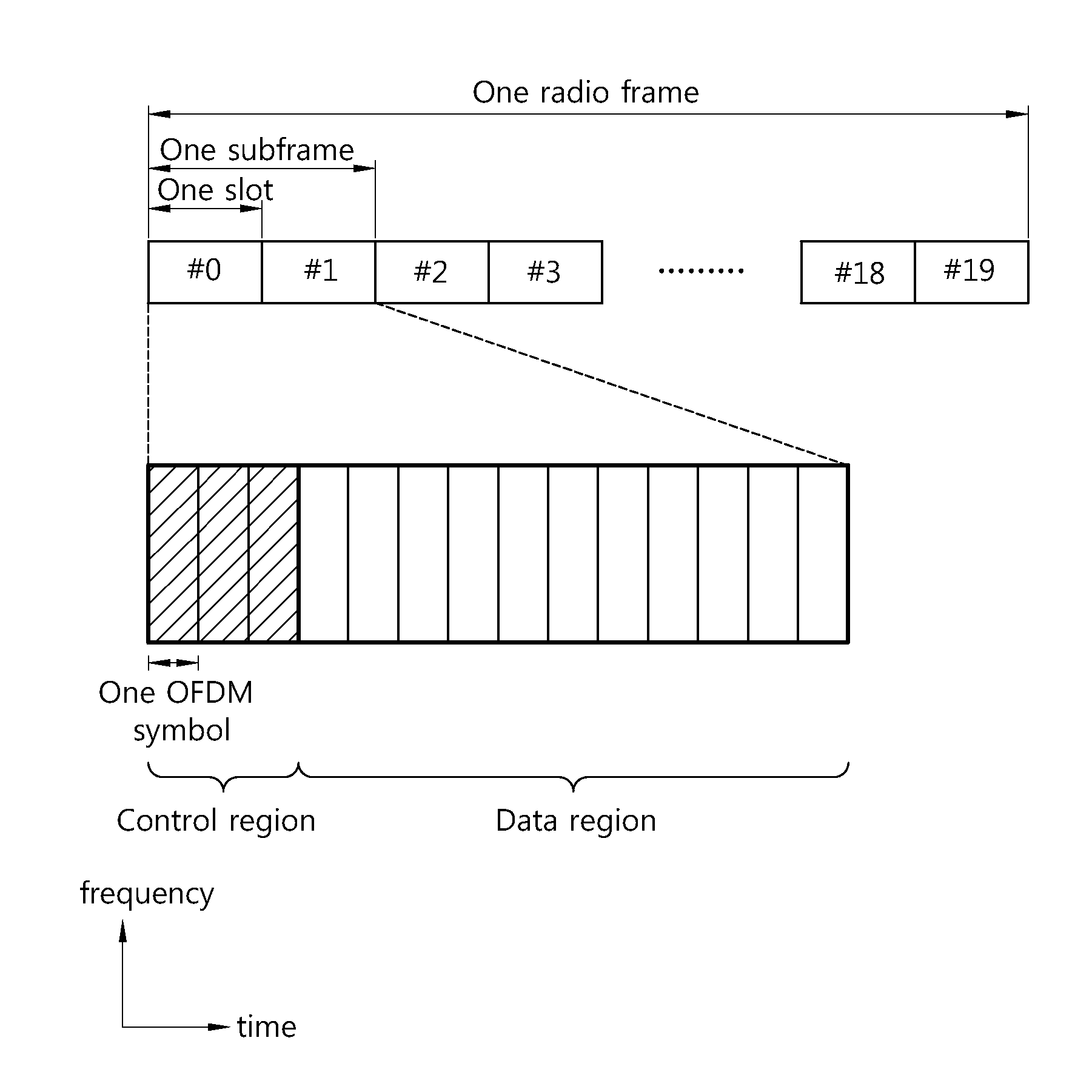
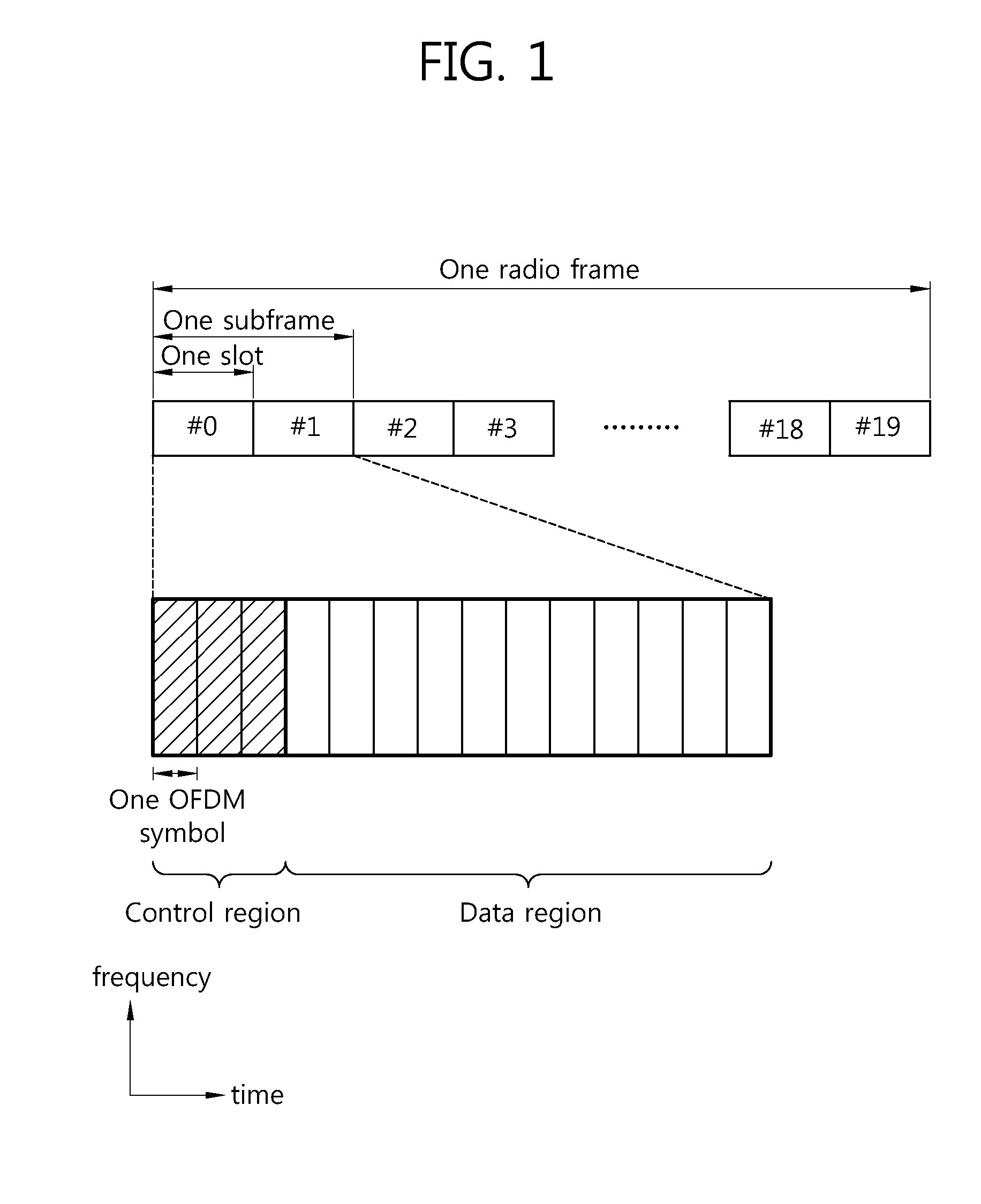
[0034]FIG. 1 shows a downlink radio frame structure in 3rd generation partnership project (3GPP) long term evolution (LTE). The section 6 of 3GPP TS 36.211 V8.7.0 (2009-05) “Evolved Universal Terrestrial Radio Access (E-UTRA); Physical Channels and Modulation (Release 8)” may be incorp...


PUM


Abstract

Discloses are a method and device for monitoring a control channel in a wireless communication system. A user equipment receives a CFI (control format indicator), indicating a size of a control region within a subframe, via a first downlink control channel and confirms whether or not an extended control region is present in the subframe. If the extended control region is present in the subframe, the user equipment monitors a PDCCH (physical downlink control channel) within the control region and the extended control region.

Description

TECHNICAL FIELD[0001]The present invention relates to wireless communications, and more particularly, to a method and apparatus for monitoring a control channel in a wireless communication system.BACKGROUND ART[0002]hu rd generation partnership project (3GPP) long term evolution (LTE) evolved from a universal mobile telecommunications system (UMTS) is introduced as the 3GPP release 8. The 3GPP LTE uses orthogonal frequency division multiple access (OFDMA) in a downlink, and uses single carrier-frequency division multiple access (SC-FDMA) in an uplink. The 3GPP LTE employs multiple input multiple output (MIMO) having up to four antennas.[0003]In recent years, there is an ongoing discussion on 3GPP LTE-advanced (LTE-A) evolved from the 3GPP LTE. The 3GPP LTE-A ensures backward compatibility with the 3GPP LTE, and supports a wideband by using carrier aggregation.[0004]The 3GPP LTE system supports only one bandwidth (i.e., one component carrier) among {1.4, 3, 5, 10, 15, 20}MHz. In orde...

Claims


Application Information

Patent Timeline
Patent Type & Authority Applications(United States)
IPC IPC(8): H04W72/04
CPCH04W48/16H04W24/00
Inventor SEO, DONG YOUNKIM, MIN GYUYANG, SUCK CHELAHN, JOON KUI
Owner LG ELECTRONICS INC
Learn More