
Vector modulator

a vector modulator and phase angle technology, applied in the field of vector modulators, can solve the problems of complex circuit configuration of the conventional vector modulator, inability to convert the phase of an input signal into all areas of the polar coordinate system, and inability to achieve the final vector sum of the phase angle output process, etc., to achieve the effect of simple system configuration and easy modulation of signals

Inactive Publication Date: 2012-11-22
LS IND SYETEMS CO LTD
View PDF6 Cites 11 Cited by
  • Summary
  • Abstract
  • Description
  • Claims
  • Application Information

AI Technical Summary

Benefits of technology

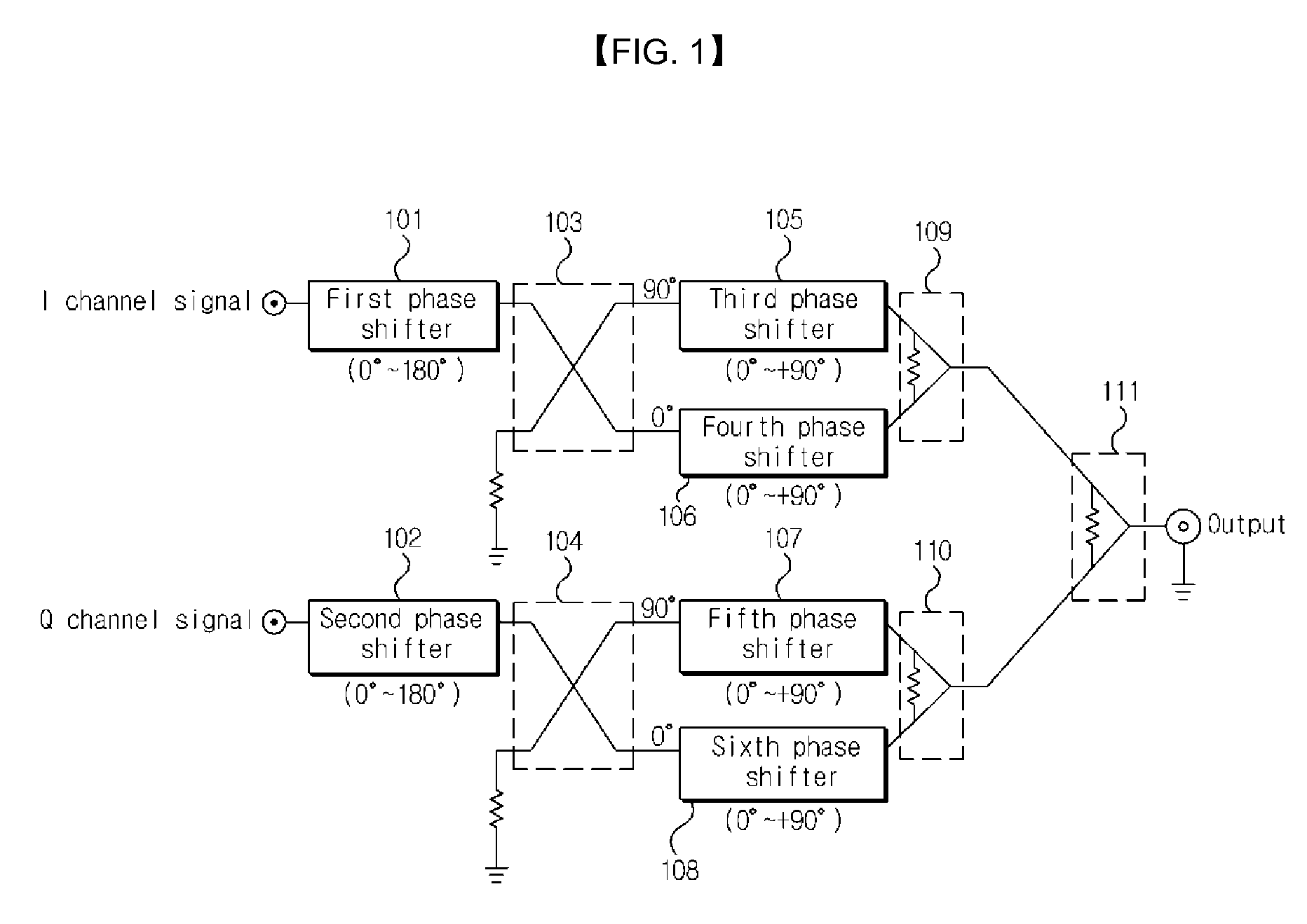
[0014]According to the present invention, the vector modulator does not use amplitude variable attenuators but uses only phase shifters, so that it is possible to simplify the configuration of a system.
[0015]Further, since an amplitude control is not performed, the modulation of a signal can be easily performed.
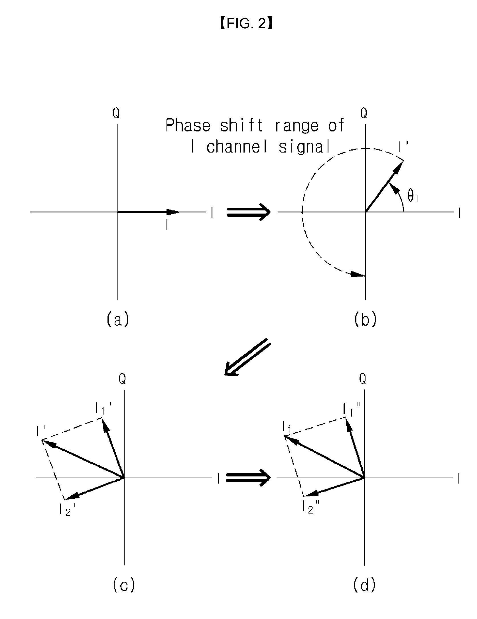
[0016]Further, the phase of an input signal can be modulated throughout all areas in the polar coordinate system.

Problems solved by technology

In this case, the amplitude variable attenuator is necessarily required in the conventional vector modulator, and therefore, the circuit configuration of the conventional vector modulator is complicated.
In order to use the amplitude variable attenuator, the conventional vector modulator has a disadvantage in that I / Q channel signals should be respectively converted into amplitude control values so as to obtain an arbitrary phase angle.
The conventional vector modulator has a problem in that the process of obtaining a phase angle output as a final vector sum is complicated.
Further, a conventional single vector modulator has a problem in that the modulation phase of a modulator is changed into two unit vectors having angles of 0 and 180 degrees, and therefore, the phase of an input signal cannot be converted into all areas in the polar coordinate system.

Method used


Image

  • Vector modulator
  • Vector modulator
  • Vector modulator

Examples


Embodiment Construction

[0023]The present invention is described more fully hereinafter with reference to the accompanying drawings, in which embodiments of the present invention are shown. This present invention may, however, be embodied in many different forms and should not be construed as limited to the embodiments set forth herein. Rather, these embodiments are provided so that this disclosure is thorough, and will fully convey the scope of the present invention to those skilled in the art.

[0024]It will be understood that, although the terms “first,”“second,” etc. may be used herein to describe various elements, these elements should not be limited by these terms. These terms are only used to distinguish one element from another element. Thus, a “first” element discussed below could also be termed as a “second” element without departing from the teachings of the present invention.

[0025]It will be understood that when an element is referred to as being “coupled” or “connected” to another element, it ca...


PUM


Abstract

Disclosed is a vector modulator. The vector modulator can control the amplitude and phase of an input signal, by not using amplitude variable attenuators but using phase shifters. Further, the vector modulator has a simple configuration and enables an input signal to be exactly modulated. Furthermore, the vector modulator can modulate the phase of an input signal throughout all areas in the polar coordinate system.

Description

TECHNICAL FIELD[0001]The present invention relates to a vector modulator, and more particularly, to a vector modulator for use in a measuring system.BACKGROUND ART[0002]In general, a vector modulator is a device that is used in a measuring machine and an amplifier, so as to simultaneously control the amplitude and phase of a signal. The vector modulator converts an input signal into an in-phase (I) channel signal and a quadrature (Q) channel signal, which have a phase difference of 90 degrees. The I / Q channel signals are output in the state in which the amplitude of each of the I / Q channel signals is not changed, but only the phase of each of the I / Q channel signals is changed depending on an external control signal. The output signals are attenuated with a certain attenuation rate by an amplitude variable attenuator and then output as a vector sum of the attenuated signals.[0003]However, a conventional vector modulator generates four uppermost signals and variably controls the ampl...

Claims


Application Information

Patent Timeline
Patent Type & Authority Applications(United States)
IPC IPC(8): H04L27/20
CPCH04L27/362H03C2200/0058H03C5/00H03C1/50
Inventor CHOI, HEON SOOCHOI, CHANG SUJEON, HYUNG JUNKIM, YEONG CHANIM, JAE HWANRUY, JUNG KI
Owner LS IND SYETEMS CO LTD
Learn More