
Grinder

Inactive Publication Date: 2012-11-22
MAKITA CORP
View PDF0 Cites 1 Cited by
  • Summary
  • Abstract
  • Description
  • Claims
  • Application Information

AI Technical Summary

Benefits of technology

[0006]In light of the above, an object of the present invention is to provide a grinder that does not have a protruding lock member, so that good operability can be maintained. Further, reliability can be ensured when a protective cover is attached.
[0012]According to the first aspect of the invention, the lock member does not protrude to the front, and thus good operability can be maintained, and also reliability can be ensured when a protective cover is attached.
[0013]According to the second aspect of the invention, in addition to the benefits of the first aspect, the urging unit can be provided in a reduced space, thereby promoting compactness of the lock mechanism.
[0014]According to the third aspect of the invention, in addition to the benefits of the first and second aspects, rattling of the protective cover is prevented due to the elastic member when the protective cover is attached.
[0015]According to the fourth aspect of the invention, in addition to the benefits of the first to third aspects, the lock member can be held at the lock released position by the regulating member, thus allowing attachment and detachment of the protective cover to / from the bearing unit to be performed easily.

Problems solved by technology

Accordingly, the protruding lock member could get caught during operation, thus impairing operability.
Further, during working, the lock member accidentally could push back toward the rear, which makes the protective cover rotate and detach.

Method used


Image

  • Grinder
  • Grinder
  • Grinder

Examples


Embodiment Construction

[0029]Hereinafter, an embodiment of the invention will be explained with reference to the figures.

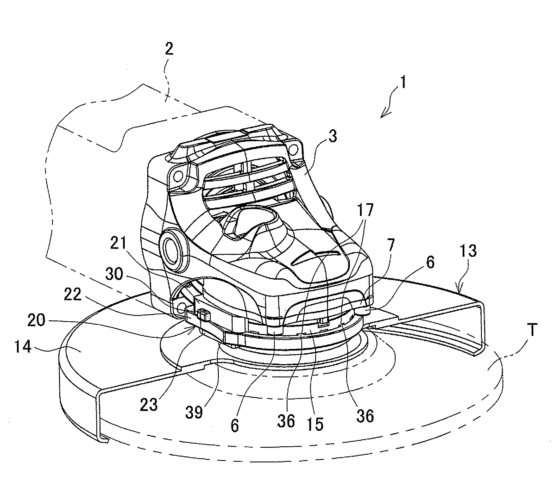
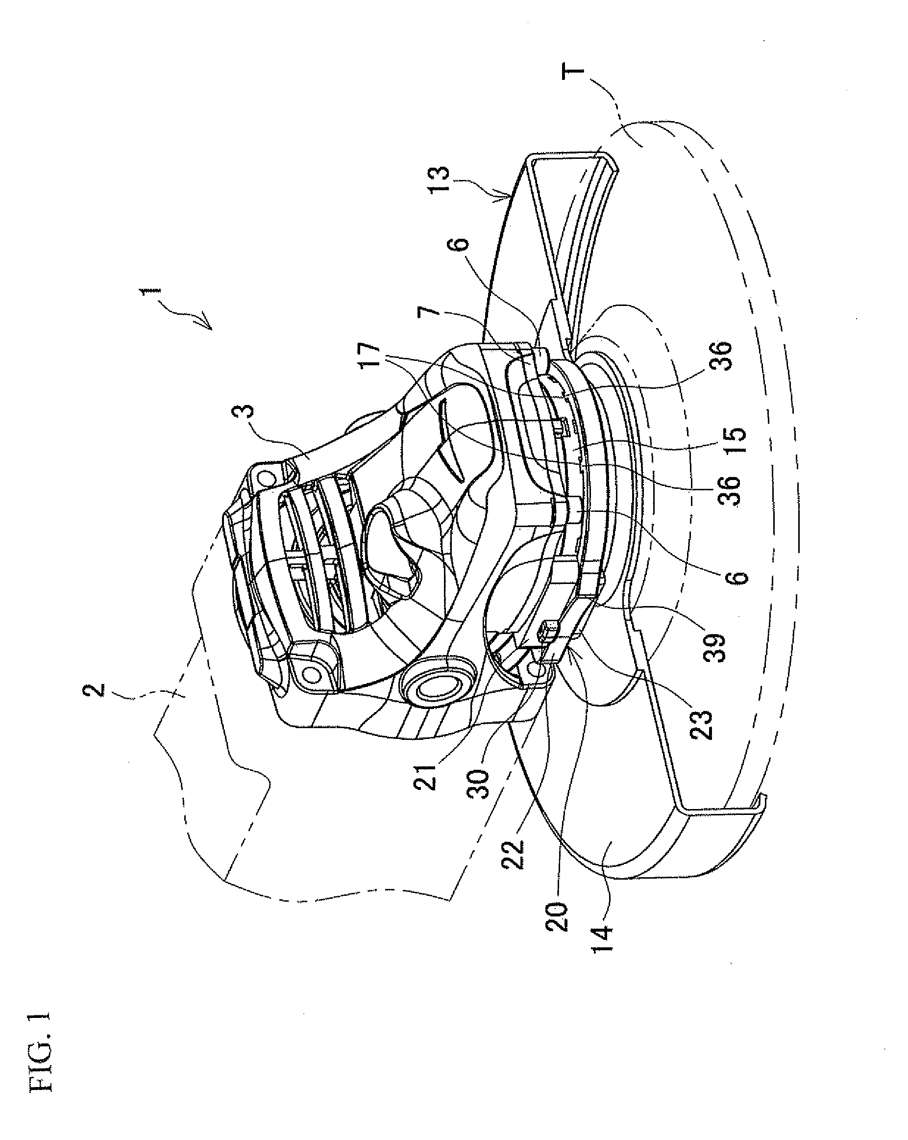
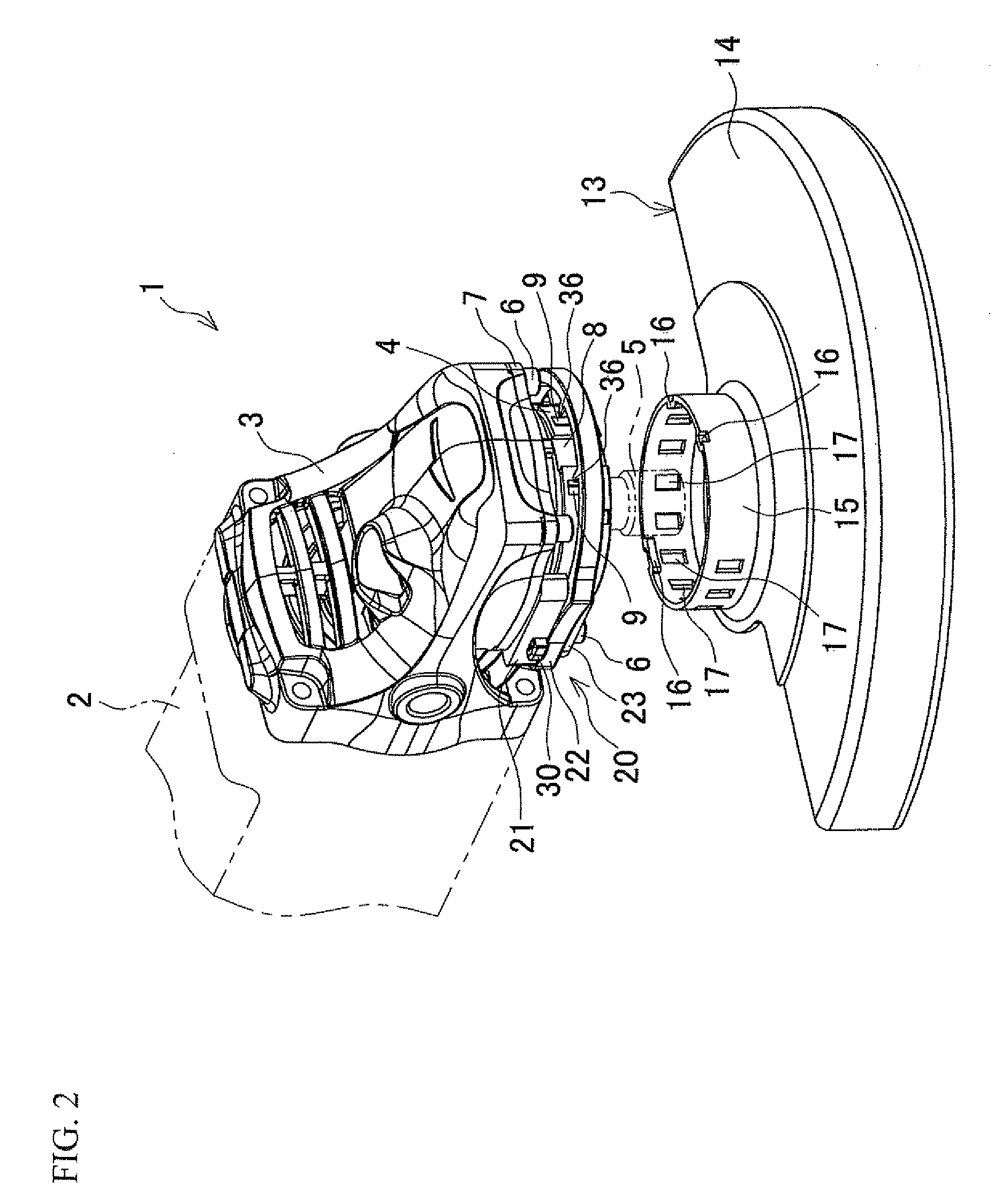
[0030]FIG. 1 to FIG. 7 show one example of a grinder. A grinder 1 includes a motor housing 2 that houses a motor, not shown in the figures, and a gear housing 3 that is connected to a front edge of the motor housing 2 and serves as a front housing. A spindle 5 is supported in a vertical direction by the gear housing 3, and a bearing box 4 is attached to a lower side of the gear housing 3 and serves as a bearing unit. The spindle 5 protrudes downwards, and a disc-shaped tool T, such as a grinding stone or diamond wheel, is detachably attached to a lower end of the spindle 5.

[0031]The bearing box 4 is shaped as a circular, cylindrical body that holds ball bearings, not shown in the figures, which support the spindle 5. Four quadrangular flanges 7 are formed in an upper edge of the bearing box 4 and fixed to a lower surface of the gear housing 3 by four bolts 6, as shown in FIG. 8. In addi...


PUM


Abstract

A grinder includes a lock mechanism, attached to a bearing box, that inhibits detachment / rotation of a cylindrical portion of a wheel cover. The lock mechanism includes a ring-shaped lock member, with a larger diameter than the cylindrical portion, that surrounds the bearing box and has a front side inner edge protruding engagement hook. The lock member can slide between a front-side lock released position at which the engagement hook is separated from the bearing box to the front side and the cylindrical portion can be attached / detached to / from the bearing box, and a rear-side locked position at which the engagement hook passes through the cylindrical portion that surrounds the bearing box and engages with a bearing box outer periphery such that a front portion is contained within a gear housing in a plan view. The lock mechanism also includes a torsion spring that urges the lock member to the locked position.

Description

BACKGROUND OF THE INVENTION[0001]This application claims the benefit of Japanese Patent Application Number 2011-109618 filed on May 16, 2011, the entirety of which is incorporated by reference.TECHNICAL FIELD[0002]The present invention relates to a grinder in which a disk-shaped tool is attached to a spindle that protrudes downward from a housing, and the housing is provided with a protective cover that covers the disk-shaped tool from above.BACKGROUND ART[0003]Conventional grinders include a spindle which protrudes downward from a housing and to which a disk-shaped tool like a grinding stone, a diamond wheel etc. is attached. The housing is provided with a protective cover that covers the disk-shaped tool attached to the spindle from above.[0004]The protective cover is attached in a removable manner using a lock mechanism that inhibits detachment and rotation, and thus angular adjustment can be made in accordance with a work operation. The lock mechanism is disclosed, for example, ...

Claims


Application Information

Patent Timeline
IPC IPC(8): B24B27/00B24B55/04
CPCB24B23/028B24B55/052
Inventor NUMATA, FUMITOSHI
Owner MAKITA CORP
Learn More