
Error determination device and error determination method of control system

a technology of error determination device and control system, which is applied in the direction of electrical control, hybrid vehicles, instruments, etc., can solve the problem that vehicles cannot be controlled accurately

Active Publication Date: 2012-11-22
TOYOTA JIDOSHA KK
View PDF3 Cites 3 Cited by
  • Summary
  • Abstract
  • Description
  • Claims
  • Application Information

AI Technical Summary

Benefits of technology

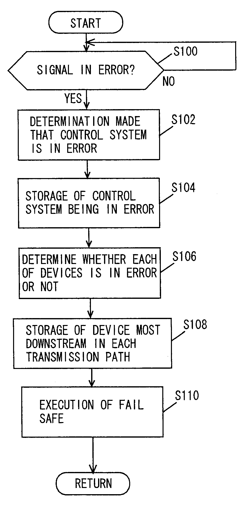
[0009]When a signal employed in the control system is in error, a determination is made that the control system is in error prior to performing the step of determining whether each of the plurality of devices transmitting the signal is in error or not. Accordingly, an error in the control system can be detected promptly. Following the determination of the control system being in error, a determination is made as to whether each of the plurality of devices transmitting a signal is in error or not. Accordingly, the site with the error can be identified. Thus, an error in the control system can be detected promptly, and the site with the error can be identified.

Problems solved by technology

If the signal processed by the ECU is in error, the vehicle cannot be controlled accurately.

Method used


Image

  • Error determination device and error determination method of control system
  • Error determination device and error determination method of control system
  • Error determination device and error determination method of control system

Examples


Embodiment Construction

[0015]An embodiment of the present invention will be described hereinafter with reference to the drawings. Hereinafter, the same elements have the same reference characters allotted, and their designation and function are also the same. Therefore, detailed description thereof will not be repeated.

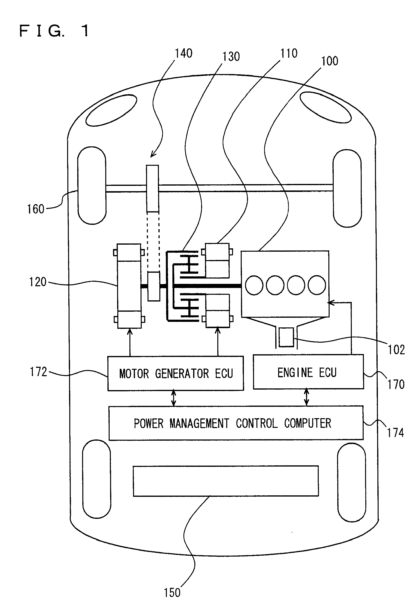
[0016]Referring to FIG. 1, a hybrid vehicle is mounted with an engine 100, a first motor generator 110, a second motor generator 120, a power split mechanism 130, a speed reducer 140, and a battery 150. Although a hybrid vehicle will be described by way of example hereinafter, an electric automobile or a fuel cell car or the like may be employed instead of a hybrid vehicle. Moreover, a general vehicle having only an engine as the driving source may be employed.

[0017]Engine 100 is controlled by an engine ECU 170. First motor generator 110 and second motor generator 120 are controlled by a motor generator ECU 172. Engine ECU 170 and motor generator ECU 172 operate based on a command value fro...


PUM


Abstract

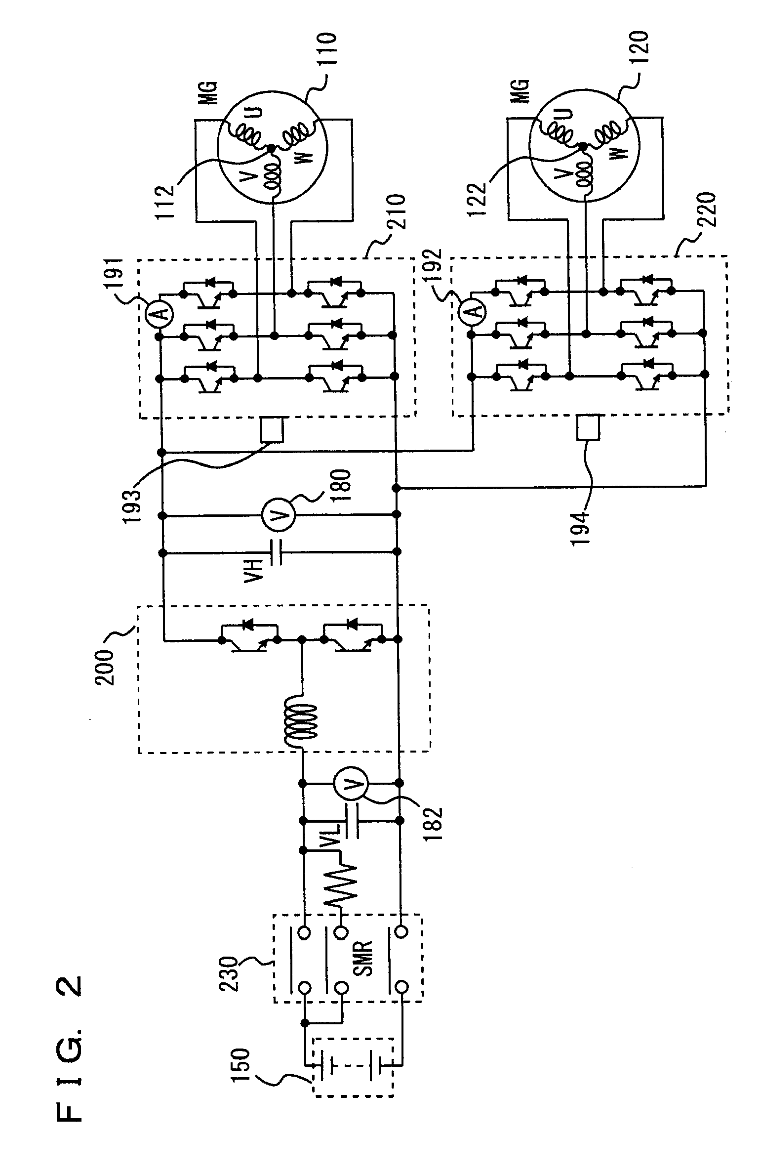
When a determination is made that a signal transmitted by a voltage sensor, a second voltage sensor, a current sensor, a temperature sensor, a second temperature sensor, a first CPU, a second CPU and a communication circuit is in error, a third CPU of a motor generator ECU determines that the control system is in error. When a determination is made that the control system is in error, the third CPU determines whether each of the voltage sensors, the current sensor, the temperature sensors, the first CPU, the second CPU and the communication circuit is in error or not.

Description

TECHNICAL FIELD[0001]The present invention relates to an in error determination device and error determination method of a control system, particularly the technique of determining an error in a control system using a signal transmitted by a plurality of devices.BACKGROUND ART[0002]A vehicle is mounted with an ECU (Electronic Control Unit) for controlling devices such as the engine and automatic transmission. An ECU is a computer including a CPU (Central Processing Unit), a ROM (Read Only Memory), a RAM (Random Access Memory), and the like. Signals detected by various sensors such as an accelerator pedal position sensor, vehicle speed sensor, temperature sensor, voltage sensor and current sensor are processed by the ECU such that a command value towards a control subject is calculated.[0003]If the signal processed by the ECU is in error, the vehicle cannot be controlled accurately. For the purpose of readily identifying a faulty site at a vehicle repair workshop or the like, it is r...

Claims


Application Information

Patent Timeline
Patent Type & Authority Applications(United States)
IPC IPC(8): G06F11/07B60L50/15
CPCB60K6/445F02D2041/227B60L3/0084B60L11/123B60L11/14B60L11/1812B60L15/007F02D41/22F02D41/266F02N11/04F02N11/10F02N2200/043F02N2200/044F02N2200/065Y02T10/6217Y02T10/6239Y02T10/7005Y02T10/7077Y02T90/127Y02T90/14Y02T90/16B60L3/0023Y02T10/7072B60L53/22B60L50/61B60L50/16Y02T10/62Y02T10/64Y02T10/70Y02T90/12
Inventor NAKAMURA, MAKOTOSOMA, TAKAYAKUTSUNA, MASAKISAKAMOTO, KENSEI
Owner TOYOTA JIDOSHA KK
Learn More