
Handle-Driven Torque Transfer Wrench having Pivotable Head

a torque transfer wrench and handle technology, which is applied in the direction of wrenches, power-driven tools, screwdrivers, etc., can solve the problems of not having a central drive shaft disclosed or contemplated, the device fails to disclose a tool that allows angular adjustment of the ratchet head with respect to his body section, and the device fails to contemplate a universal joint within the body of the tool, etc., to facilitate the rotation of the fastener head

Inactive Publication Date: 2012-11-29
SPATA JOSEPH
View PDF5 Cites 21 Cited by
  • Summary
  • Abstract
  • Description
  • Claims
  • Application Information

AI Technical Summary

Benefits of technology

[0014]It is another object of the present invention to provide an improved torque transfer wrench that facilitates rotation of a fastener head within confined and blind areas, particularly in automotive applications wherein fastener access and engine bay space is limited.

Problems solved by technology

These devices fail to disclose or contemplate the use of a central drive shaft that incorporates a pivotable universal joint that alters the torque transmission path with respect to the handle and ratcheting head directions.
While providing a tool that allows offset input, the Walter device fails to disclose a tool that allows angular adjustment of the ratchet head with respect to his body section.
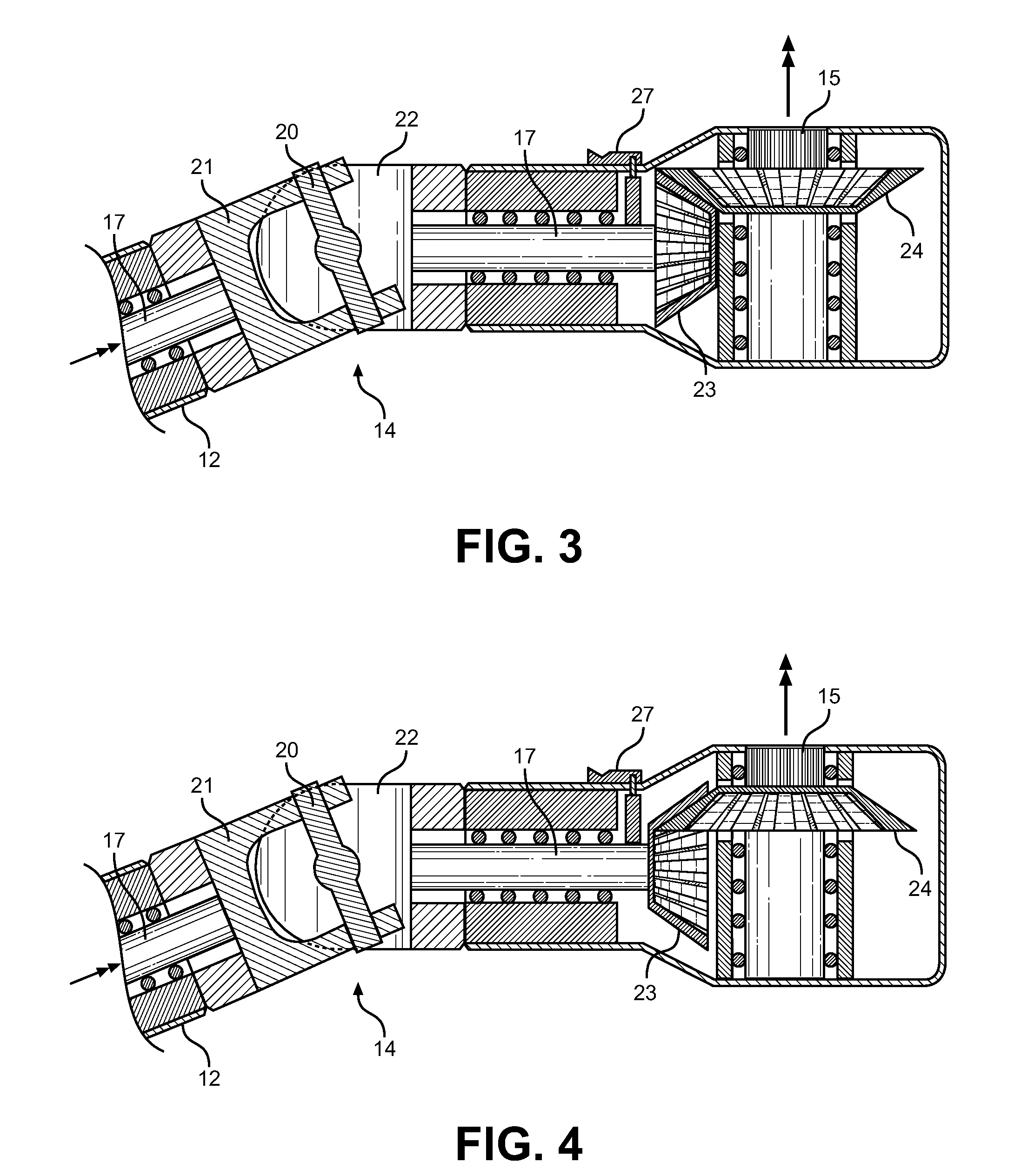
These devices fail to contemplate a universal joint within the body of the tool, wherein the driveshaft is permitted to transmit torque at an angle with respect to its input direction.
This facilitates the driving of fastener heads in extremely confined and hidden locations, wherein perpendicular positioning of the tool is not possible due to space limitations, and further rotation of a standard wrench handle is not efficient or possible.

Method used


Image

  • Handle-Driven Torque Transfer Wrench having Pivotable Head
  • Handle-Driven Torque Transfer Wrench having Pivotable Head
  • Handle-Driven Torque Transfer Wrench having Pivotable Head

Examples


Embodiment Construction

[0026]Reference is made herein to the attached drawings. Like reference numerals are used throughout the drawings to depict like or similar elements of the torque transmission wrench. For the purposes of presenting a brief and clear description of the present invention, the preferred embodiment will be discussed as used for applying torque to a rotary fastener in confined and blind locations. The figures are intended for representative purposes only and should not be considered to be limiting in any respect.

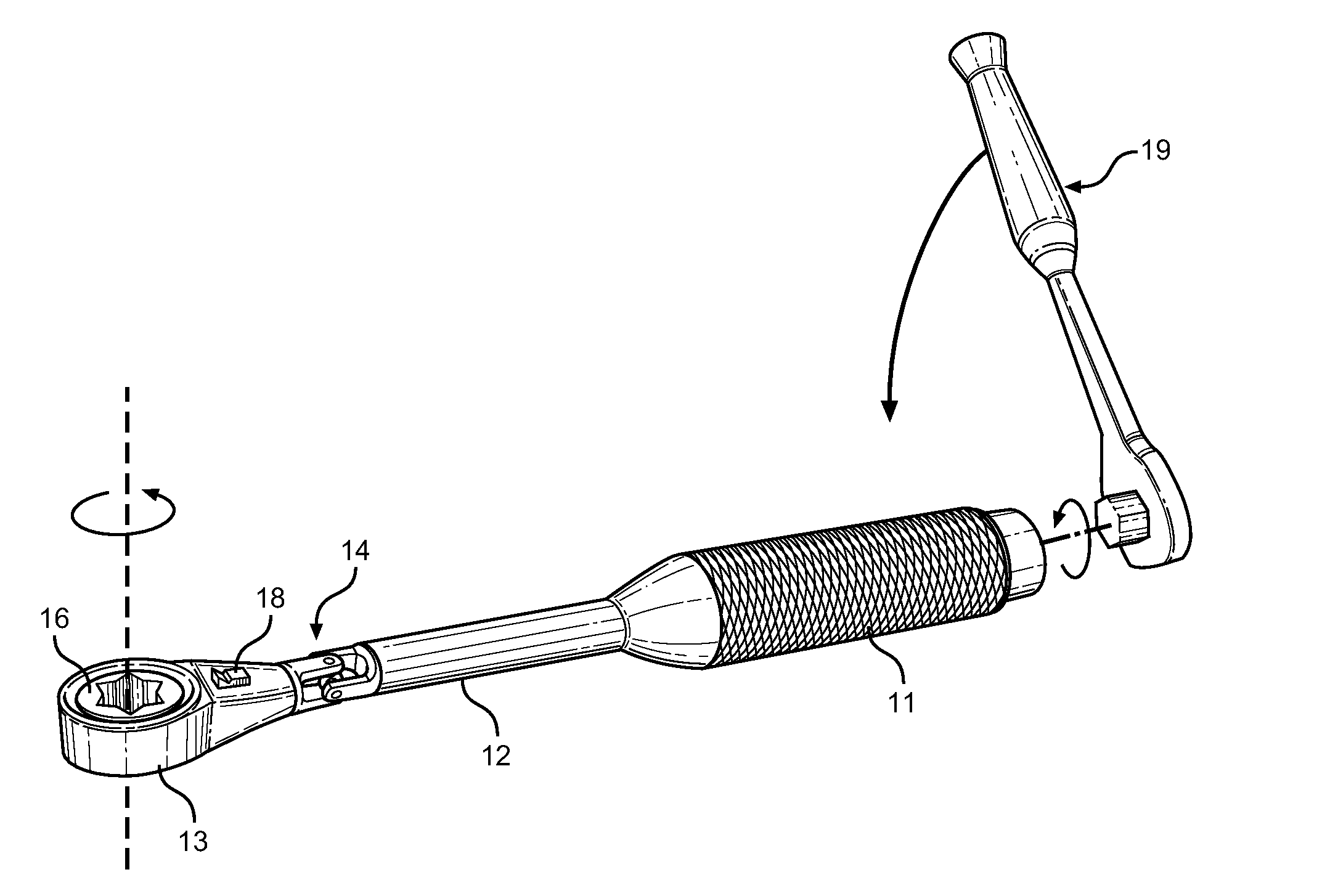
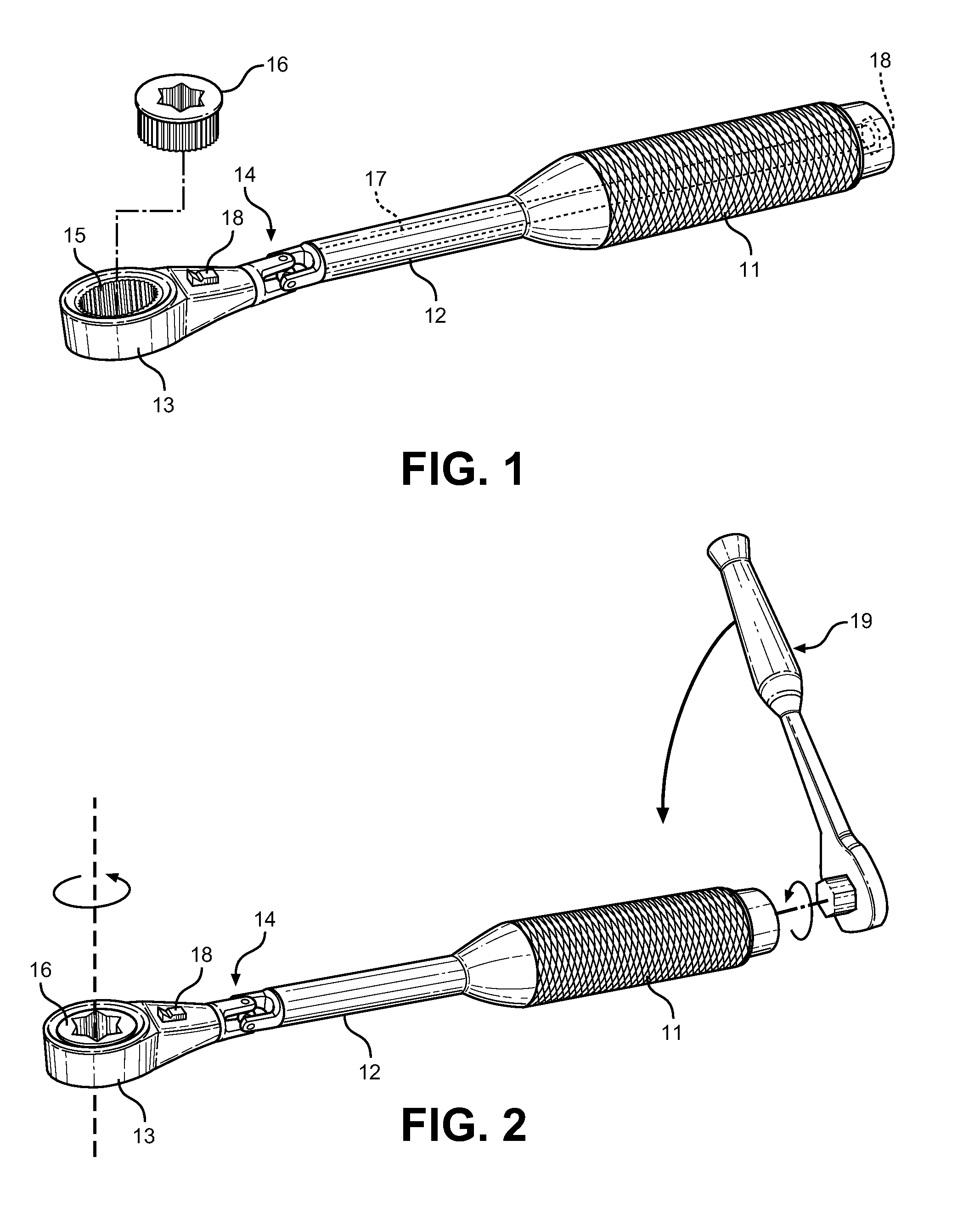
[0027]Referring now to FIG. 1, there is shown a perspective view of the torque transmission wrench tool of the present invention, wherein a socket 16 is shown in an exploded configuration with respect to the head 13 of the tool. The wrench itself comprises an elongated body having a handle section 11 and a ratcheting head section 13. The handle end 11 includes a torque input 18 at its proximal end, wherein another input tool, such as a ratchet or screw driver, applies torque thro...


PUM


Abstract

Disclosed is a torque transfer device, comprising a body section, a rotary head section and an internal driveshaft within the body section for coupling rotational input through the body to the head section at an angle with respect to the drive direction. The body section comprises a rotational drive input that connects to an internal driveshaft. The body section terminates, allowing the driveshaft to continue into a universal pivot joint, which further connects to the head section having an internal rotary ratchet transmission and socket-accepting inner portion. As the input is rotated, the driveshaft rotates the ratchet head, providing a tool that allows directional variation with regard to input and output torque transmission. The universal joint allows the head section to be further rotated with respect to the body section for improved torque input onto fastener heads in enclosed or shrouded locations.

Description

CROSS REFERENCE TO RELATED APPLICATION[0001]This application claims the benefit of U.S. Provisional Application No. 61 / 489,089 filed on May 23, 2011, entitled “Powerwrench.”BACKGROUND OF THE INVENTION[0002]1. Field of the Invention[0003]The present invention relates to ratcheting box wrenches, spanners and wrench tools for inputting torque onto a fastener head within confined spaces having minimal clearance for tool rotation. More specifically, the present invention pertains to a ratcheting box wrench having a handle drive mechanism that allows rotational input through the handle to affect a rotation at the wrench working end, between which is a universal joint that allows misalignment of the wrench head with its shaft body for improved access to fastener heads within confined areas.[0004]Box wrenches and ratcheting mechanisms are well known in the art of mechanical and automotive tools. These devices allow a user to obtain purchase on a fastener nut and apply a torque thereto for t...

Claims


Application Information

Patent Timeline
IPC IPC(8): B25B23/142B25B13/46B25B17/00
CPCB25B13/463B25B23/142B25B23/0014B25B17/02
Inventor SPATA, JOSEPH
Owner SPATA JOSEPH
Learn More