Methods For Characterization Of Formations, Navigating Drill Paths, And Placing Wells In Earth Boreholes

a technology of formation and well, which is applied in the direction of survey, directional drilling, borehole/well accessories, etc., can solve the problems that seismic surveys are generally incapable of providing the desired resolution and accuracy

Active Publication Date: 2012-11-29
SCHLUMBERGER TECH CORP
View PDF2 Cites 55 Cited by
  • Summary
  • Abstract
  • Description
  • Claims
  • Application Information

AI Technical Summary

Problems solved by technology

However, seismic surveys are generally incapable of providing the desired resolution and accuracy t

Method used


Image

  • Methods For Characterization Of Formations, Navigating Drill Paths, And Placing Wells In Earth Boreholes
  • Methods For Characterization Of Formations, Navigating Drill Paths, And Placing Wells In Earth Boreholes
  • Methods For Characterization Of Formations, Navigating Drill Paths, And Placing Wells In Earth Boreholes

Examples


Embodiment Construction

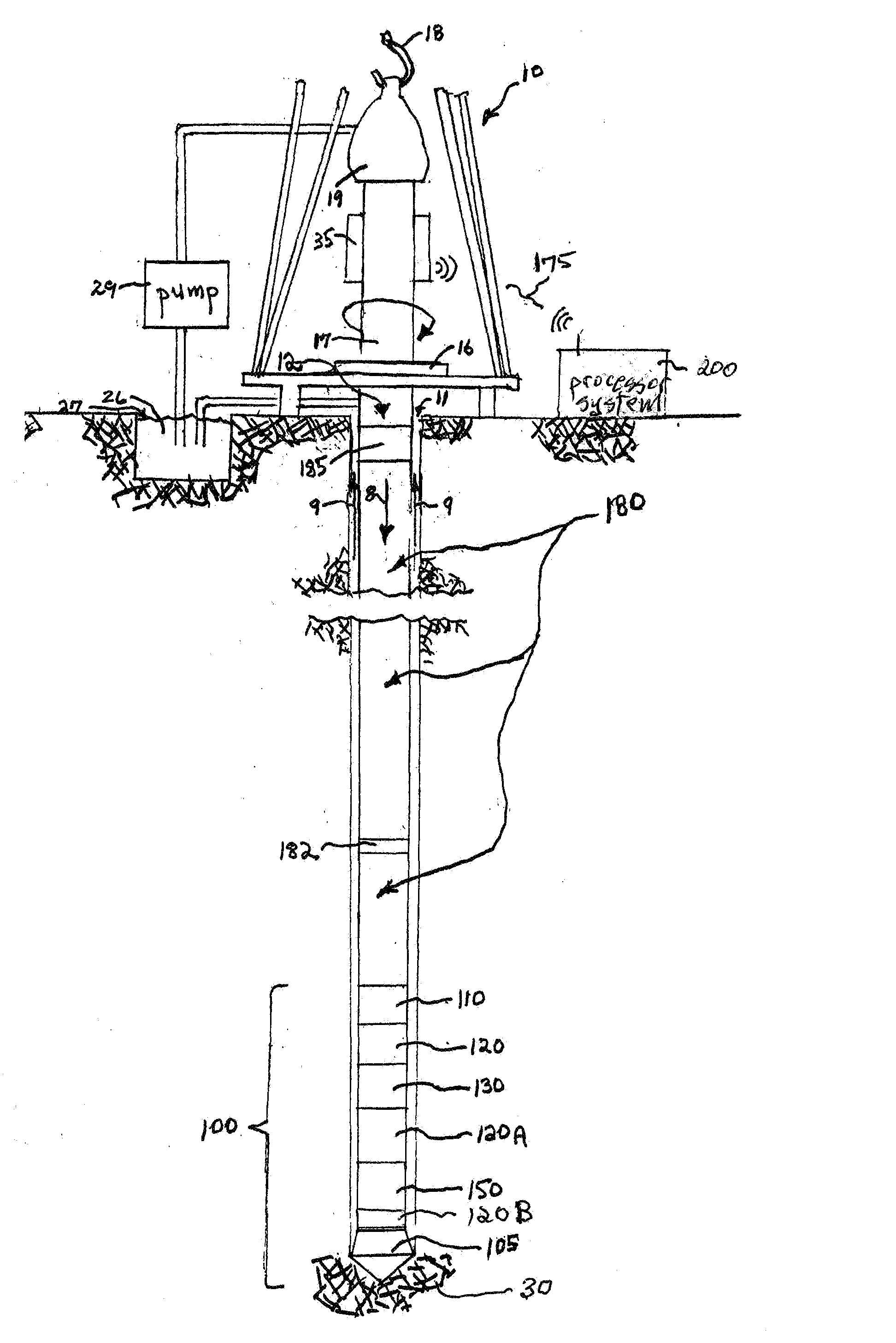
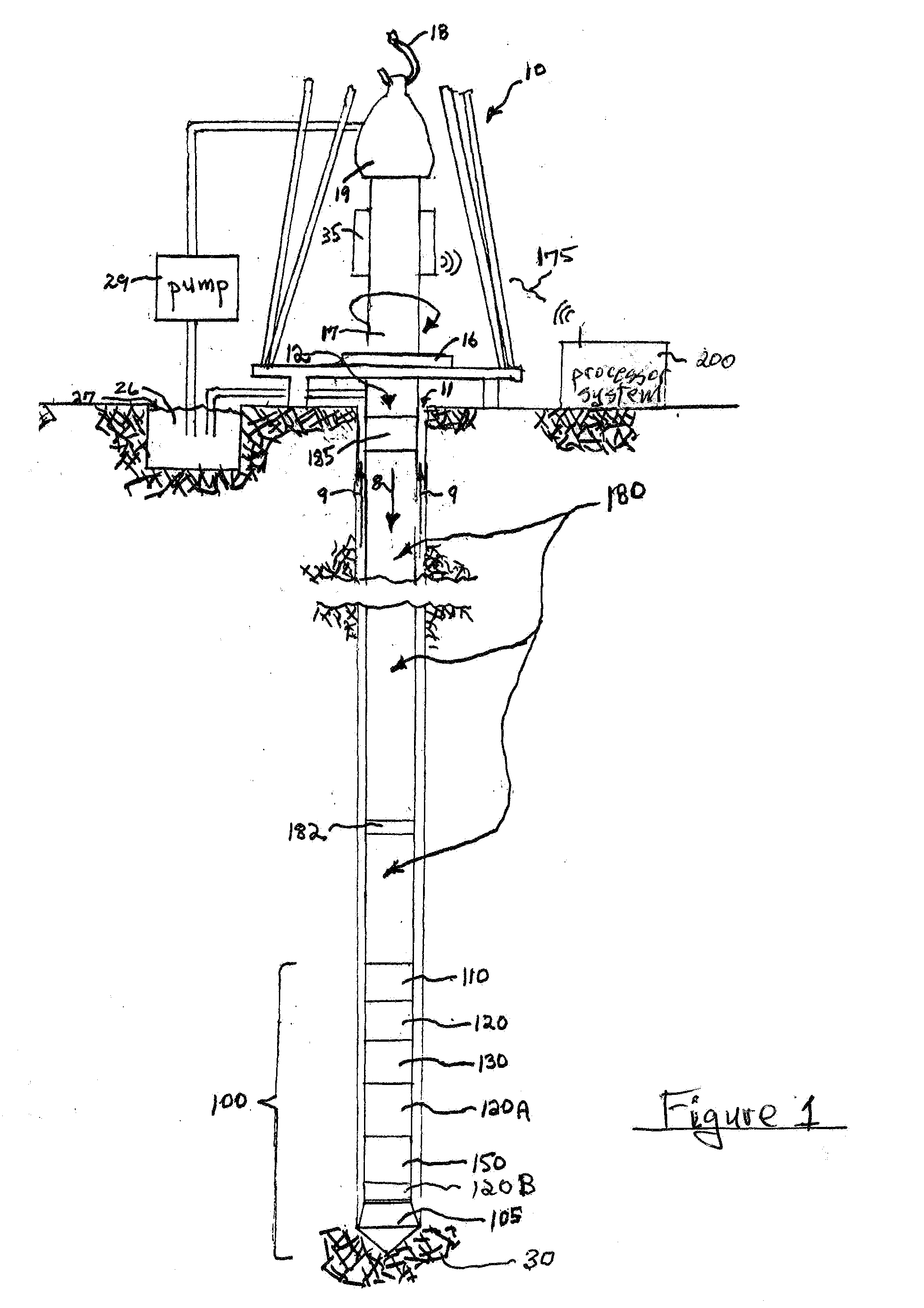
[0068]FIG. 1 illustrates a wellsite system in conjunction with which the present invention can be practiced. The wellsite can be onshore or offshore. In this exemplary system, a borehole 11 is formed in subsurface formations 30 by rotary directional drilling.

[0069]A drill string 12 is suspended within the borehole 11 and has a bottom hole assembly 100 which includes a drill bit 105 at its lower end. The surface system includes platform and derrick assembly 10 positioned over the borehole 11, the assembly 10 including a rotary table 16, kelly 17, hook 18 and rotary swivel 19. The drill string 12 is rotated by the rotary table 16, energized by means not shown, which engages the kelly 17 at the upper end of the drill string. The drill string 12 is suspended from a hook 18, attached to a traveling block (also not shown), through the kelly 17 and a rotary swivel 19 which permits rotation of the drill string relative to the hook. As is well known, a top drive system could alternatively be...


PUM


Abstract

A method for directing bore-hole drilling in a target earth formation includes the following steps: providing drilling equipment having a bottom hole assembly that includes a controllable directional drilling subsystem, and a logging-while-drilling directional measurement tool with a look-around and look-ahead capability; determining the presence of a predetermined type of formation characteristic in the target formation; and navigating a drill path in the target formation with the drilling equipment, including receiving measurement signals from the directional measurement tool, obtaining, from the received measurement signals, indications of formation parameters with respect to the formation characteristic in the target formation, and controlling the directional drilling subsystem to drill in a direction determined as a function of the obtained indication of formation parameters.

Description

PRIORITY CLAIM Priority is claimed from U.S. Provisional Patent Application No. 61 / 253,248, filed Oct. 20, 2009 which is incorporated herein by reference.FIELD OF THE INVENTION[0001]This invention relates to the field of drilling and measuring in earth boreholes and, more particularly, to methods for characterizing target earth formations and for accurately placing wells, such as during directional drilling of boreholes.BACKGROUND OF THE INVENTION[0002]The advent of directional drilling, and of logging while drilling (“LWD”) and measurement while drilling (“MWD”), have profoundly improved the locating and placement of wells for production of hydrocarbon resources. Directional drilling involves the drilling of a well bore along a deviated course for various purposes, including bottoming out in a particular target region. Directional drilling is employed, for example, to obtain an appropriate well bore trajectory into an oil producing formation bed (or “pay zone”) and then drill subst...

Claims


Application Information

Patent Timeline
IPC IPC(8): E21B44/00E21B47/00E21B7/06G06N5/02G06F17/00
CPCE21B47/02E21B7/06G01V3/20E21B47/026
Inventor SEYDOUX, JEANCHOW, YUK HA
Owner SCHLUMBERGER TECH CORP
Why Eureka
Try Eureka