Disc brake apparatus

a disc brake and disc technology, applied in the direction of braking systems, fluid actuated brakes, transportation and packaging, etc., can solve the problems of unstable brake pad behavior, brake pad unstability, associated brake noise, etc., to reduce the cost of machining, reduce the effect of brake pad noise, and stable brake pad behavior

Inactive Publication Date: 2012-11-29
ADVICS CO LTD
View PDF83 Cites 9 Cited by
  • Summary
  • Abstract
  • Description
  • Claims
  • Application Information

AI Technical Summary

Benefits of technology

[0004]In the disc brake apparatus described in Patent Document 1 mentioned above, torque associated with braking is received mainly by the torque reception surfaces (planes) which are formed on the caliper and engaged with the respective end surfaces (planes) formed on end portions, located toward the trailing side of the linings with respect to the circumferential direction of the disc rotor, of the back plates. The torque reception surfaces (planes) are such unstable planes as to easily vary in geometry according to an engagement relation between the radially inner support shaft and the radially inner engagement surfaces of the back plates (manufacturing errors, assembly errors, or thermal expansion of the members) or the like, and thus involve difficulty in planar engagement with the end surfaces (planes) of the back plates. Therefore, during braking, the brake pads may behave unstably, and associated brake noise may be produced. Also, the disc brake apparatus requires machining for forming the torque reception surfaces on the caliper and machining of the entire trailing-side end surfaces (planes) of the back plates; therefore, a machining area is large, resulting in an increase in cost.

Problems solved by technology

The torque reception surfaces (planes) are such unstable planes as to easily vary in geometry according to an engagement relation between the radially inner support shaft and the radially inner engagement surfaces of the back plates (manufacturing errors, assembly errors, or thermal expansion of the members) or the like, and thus involve difficulty in planar engagement with the end surfaces (planes) of the back plates.
Therefore, during braking, the brake pads may behave unstably, and associated brake noise may be produced.
Also, the disc brake apparatus requires machining for forming the torque reception surfaces on the caliper and machining of the entire trailing-side end surfaces (planes) of the back plates; therefore, a machining area is large, resulting in an increase in cost.
Therefore, the distribution of surface pressure on each of the linings against the disc rotor is inconsistent, unavoidably resulting in uneven wear of the linings in the circumferential direction of the rotor disc.
The above-proposed disc brake apparatus can solve the above problem, but involves a problem that, in some cases, the production of brake noise in braking cannot be sufficiently solved; therefore, demand exists for further improvement.

Method used


Image

  • Disc brake apparatus
  • Disc brake apparatus
  • Disc brake apparatus

Examples


Embodiment Construction

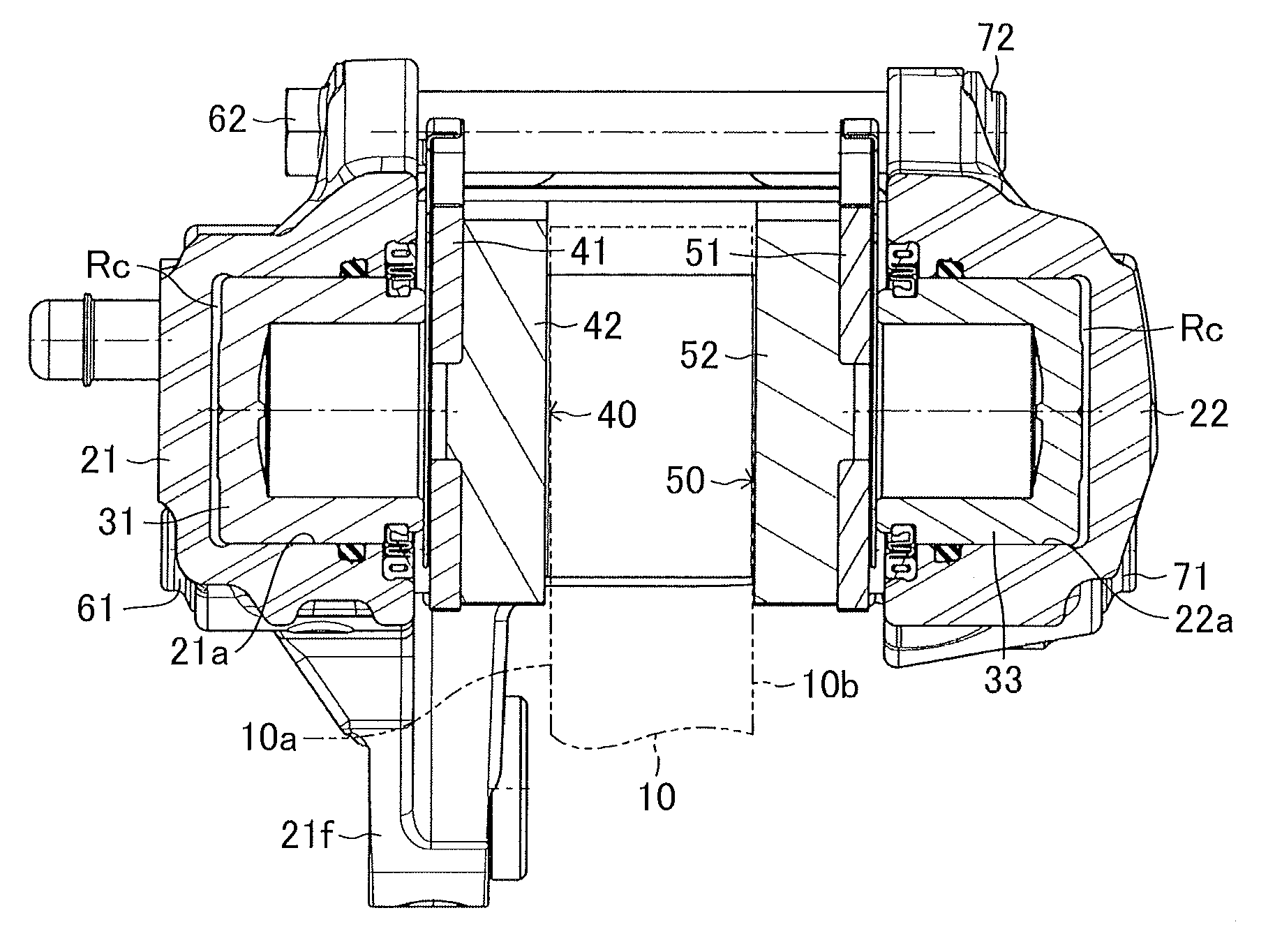
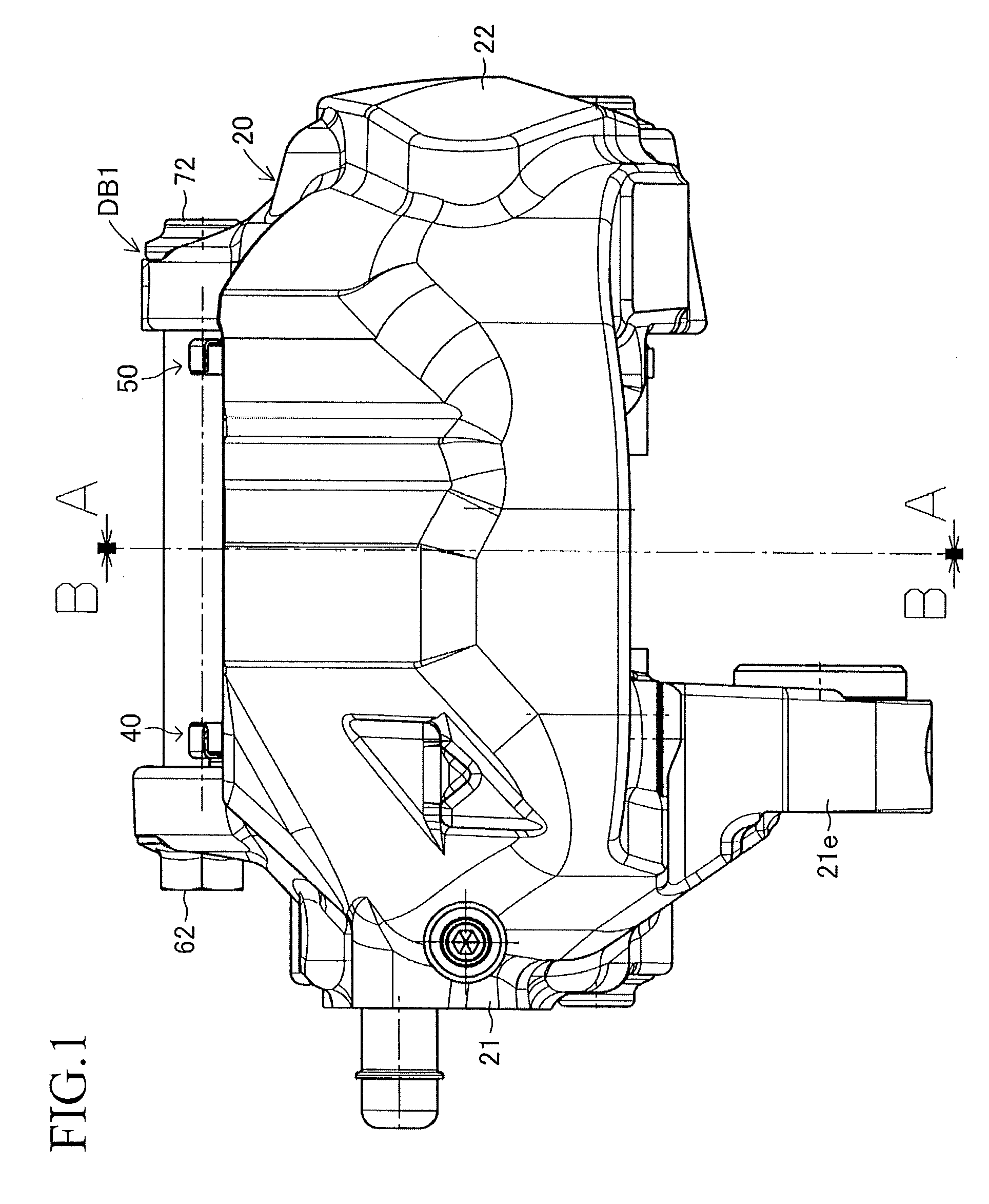
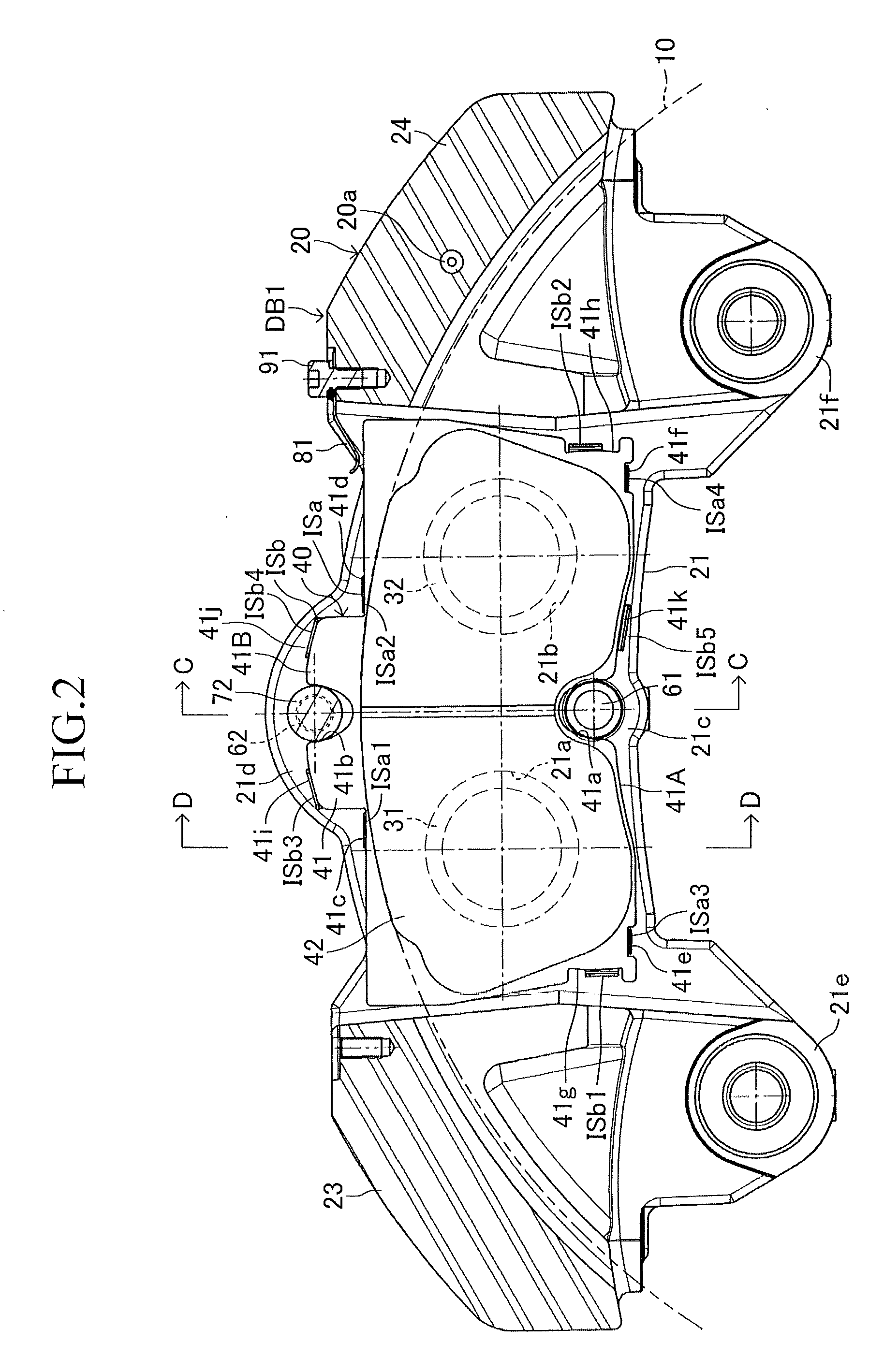
[0030]The embodiments of the present invention will next be described with reference to the drawings. FIGS. 1 to 6 show an embodiment of the present invention embodied in an opposed-piston type (stationary type) disc brake apparatus for a vehicle. A disc brake apparatus DB1 of the present embodiment includes a disc rotor 10 which is attached to an axle hub (an unillustrated rotating member) and rotates unitarily with a wheel (not shown); a caliper 20 disposed in such a manner as to straddle a partial circumference of the disc rotor 10; four pistons 31, 32, 33, and 34 attached to the caliper 20; an inner brake pad 40; an outer brake pad 50; an inner shim ISa and an outer shim ISb attached to the inner brake pad 40; and an inner shim OSa and an outer shim OSb attached to the outer brake pad 50. The disc brake apparatus DB1 further includes an inner radially-inner support shaft 61 and an inner radially-outer support shaft 62 provided on the caliper 20; an outer radially-inner support s...


PUM


Abstract

A back plate is biased radially inward of a disc rotor by a spring, engaged at two locations on a torque reception surface with a caliper support shaft, and engaged at one location on a torque reception surface with a caliper support shaft. Inner and outer shims are disposed toward a back plate and pistons, respectively, and a friction factor between the back plate and the inner shim and that between the pistons and the outer shim are higher than that between the inner and outer shims. The inner shim is movable with the back plate in radial and circumferential directions and is movable relative to the back plate in the axial direction, and the outer shim is movable with the back plate in radial and circumferential directions, is movable relative to the back plate in the axial direction, and is rotatable about the radially inner support shaft axis.

Description

TECHNICAL FIELD[0001]The present invention relates to a disc brake apparatus, and more particularly to a disc brake apparatus including a disc rotor which is attached to a rotating member (e.g., an axle hub) and rotates unitarily with the rotating member, a caliper attached to a support body (e.g., a vehicle body) in such a manner as to straddle a partial circumference of the disc rotor, a pair of brake pads disposed in such a manner as to be able to nip the disc rotor and supported, via support shafts, by the caliper in such a manner as to be movable in the axial direction of the disc rotor, and pistons attached to the caliper and adapted to press the brake pads toward the disc rotor; and configured such that the pistons press back plates of the brake pads, whereby the linings of the brake pads are slidably pressed against the braking surfaces of the disc rotor, thereby braking the disc rotor.BACKGROUND ART[0002]In a disc brake apparatus of such a type described in, for example, Pa...

Claims


Application Information

Patent Timeline
Patent Type & Authority Applications(United States)
IPC IPC(8): F16D65/095B60T1/06F16D55/228
CPCF16D2121/02F16D2055/0091F16D65/095F16D2055/007F16D65/0977
Inventor OGAWA, MASAHARU
Owner ADVICS CO LTD
Why Eureka
Try Eureka