Method of and a welding station for laying a pipeline, with pipe section welded together by internal and external welding

a welding station and pipe section technology, applied in the field of apparatus and methods for welding together clad pipe sections, can solve the problems of irregular, undesirable welds, difficult to achieve reliably, etc., and achieve the effect of improving overall weld quality and reducing the chance of welds

Active Publication Date: 2012-11-29
SAIPEM SPA
View PDF18 Cites 18 Cited by
  • Summary
  • Abstract
  • Description
  • Claims
  • Application Information

AI Technical Summary

Benefits of technology

[0008]The present invention provides a method of laying a pipeline, in which pipe sections are welded together to form the pipeline. It will be appreciated that the pipe sections and the pipeline may be referred to simply as pipes. The method includes the steps of providing a pipe section to be welded to the end of a pipeline, arranging the pipe section adjacent to the end of the pipeline thereby defining a circumferential joint to be welded, performing an external weld pass on the root of the joint to be welded during which weld material is deposited in the root of the joint to be welded, thereby forming a root weld, and performing an internal weld pa

Problems solved by technology

Such remelting of the root-weld can improve the chance of achieving full fusion at the root of the weld joint, which can otherwise be difficult to achieve r

Method used


Image

  • Method of and a welding station for laying a pipeline, with pipe section welded together by internal and external welding
  • Method of and a welding station for laying a pipeline, with pipe section welded together by internal and external welding
  • Method of and a welding station for laying a pipeline, with pipe section welded together by internal and external welding

Examples


Embodiment Construction

[0043]The presently described embodiment of the invention concerns the butt-welding together of Corrosion Resistant Alloy (CRA) clad pipe sections during a method of laying an underwater pipeline from a floating vessel. The pipeline is laid overboard a vessel by welding successive sections of pipe to the end of the pipeline. When laying a pipeline, the tension in the pipeline being laid is significant and is typically of the order of several hundreds of kilo-Newtons. During laying and subsequent use of the pipeline, the pipe joints may be subject to fatigue loading.

[0044]It is therefore of particular importance to ensure that the joints between the sections of pipe that make up the pipeline are of a very high quality. Failure of any joint in the pipeline after the joint has been lowered from the vessel into the water can be possibly dangerous and extremely costly.

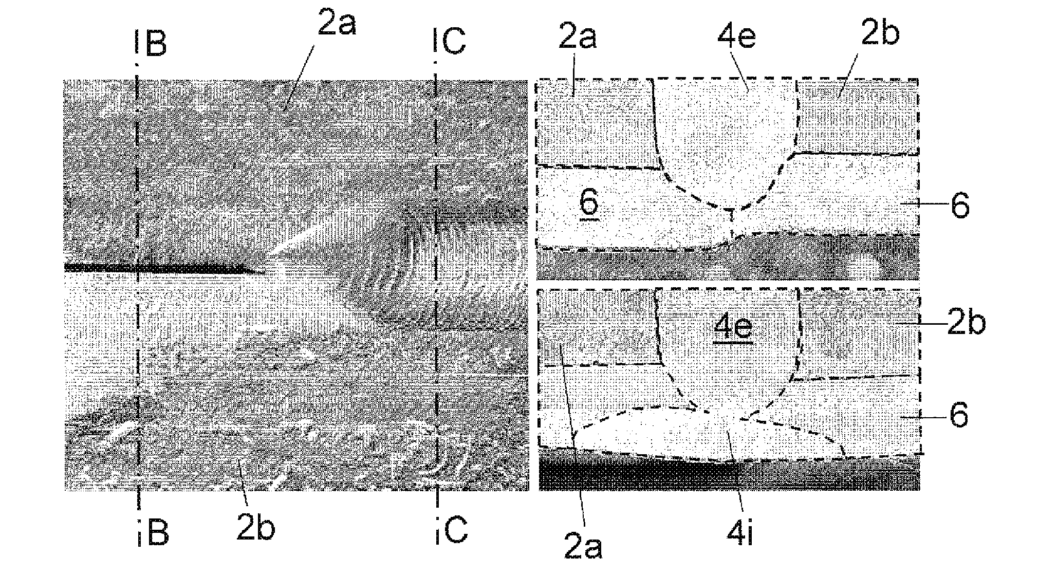
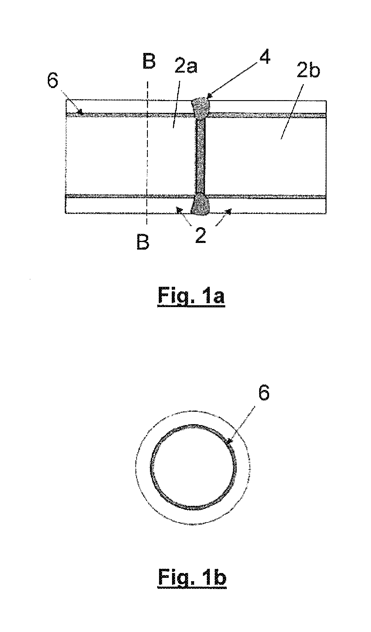
[0045]FIG. 1a shows two pipe sections 2 in longitudinal cross-section. There is a first pipe section 2a connected to a se...


PUM

PropertyMeasurementUnit
Shapeaaaaaaaaaa
Metallic bondaaaaaaaaaa
Corrosion resistanceaaaaaaaaaa

Abstract

A method of laying a pipeline is described in which both internal and external weld passes are performed in order to weld together the pipe sections. The method includes arranging a pipe section adjacent to the end of a pipeline thereby defining a circumferential joint to be welded, performing an external weld pass, with for example GMAW—MIG torches, on the root of the joint to be welded during which weld material is deposited in the root of the joint to be welded, thereby forming a root weld, and then performing an internal weld pass, with for example a GTAW—TIG torch, on the root weld during which the root weld is melted and re-shaped. The method has particular application in relation to pipes clad with corrosion resistant alloy.

Description

BACKGROUND OF THE INVENTION[0001]The present invention relates to an apparatus and method for welding pipes together. In particular, but not exclusively, the invention relates to welding together clad pipe sections, or other multilayer pipe sections, when laying pipelines underwater at sea.[0002]When laying a pipeline at sea from a pipe-laying vessel, one end of the pipeline (sometimes referred to as the “pipe string”) is held by the vessel and a pipe section is welded to the end of the pipeline. The pipeline and newly welded pipe section are then fed out from the vessel, so that the process can be repeated. The weld joint must be of high quality in view of the high tensile loads to which the pipeline is subjected during the laying process. Quality of weld joints is critical when the pipeline will, once installed, be in a position where it is exposed to regular changing motion in the sea (for example when the pipeline is in the form of a catenary riser). In such case, the weld joint...

Claims


Application Information

Patent Timeline
IPC IPC(8): B23K31/02B23K10/02B23K9/00B23K31/12B23K37/053
CPCB23K9/0284B23K9/0286B23K9/167B23K9/1735B23K9/0213B23K2201/10C21D9/50F16L13/02B23K37/0276B23K2101/10B23K10/02
Inventor BOWERS, JONATHAN
Owner SAIPEM SPA
Why Eureka
Try Eureka