
Bidirectional hysteretic power converter

a power converter and hysteretic technology, applied in the direction of electric variable regulation, process and machine control, instruments, etc., can solve the problems of buck converter control quite different from the control of buck converter, rhpz can complicate the stability of the loop, and the overall response of the boost converter is quite slow, so as to reduce the value, size and cost of its passive components

Active Publication Date: 2012-11-29
QUALCOMM INC
View PDF4 Cites 41 Cited by
  • Summary
  • Abstract
  • Description
  • Claims
  • Application Information

AI Technical Summary

Benefits of technology

The present invention provides an improved design for a power converter that allows it to work efficiently in two different modes (hence the name hysteretic). This means that we can use smaller parts and reduce costs while still getting good performance from our converters.

Problems solved by technology

The technical problem addressed in this patent is how to create a biddirectional power converter that can operate efficiently at high speeds with hysteretic control. Additionally, the patent discusses the difficulty of achieving optimal performance in either Constant Current Model (CCM) or Discontinuous Conduction Module (DCM), and proposes solutions to address each issue separately.

Method used


Image

  • Bidirectional hysteretic power converter
  • Bidirectional hysteretic power converter
  • Bidirectional hysteretic power converter

Examples


Embodiment Construction

A FIG. 2

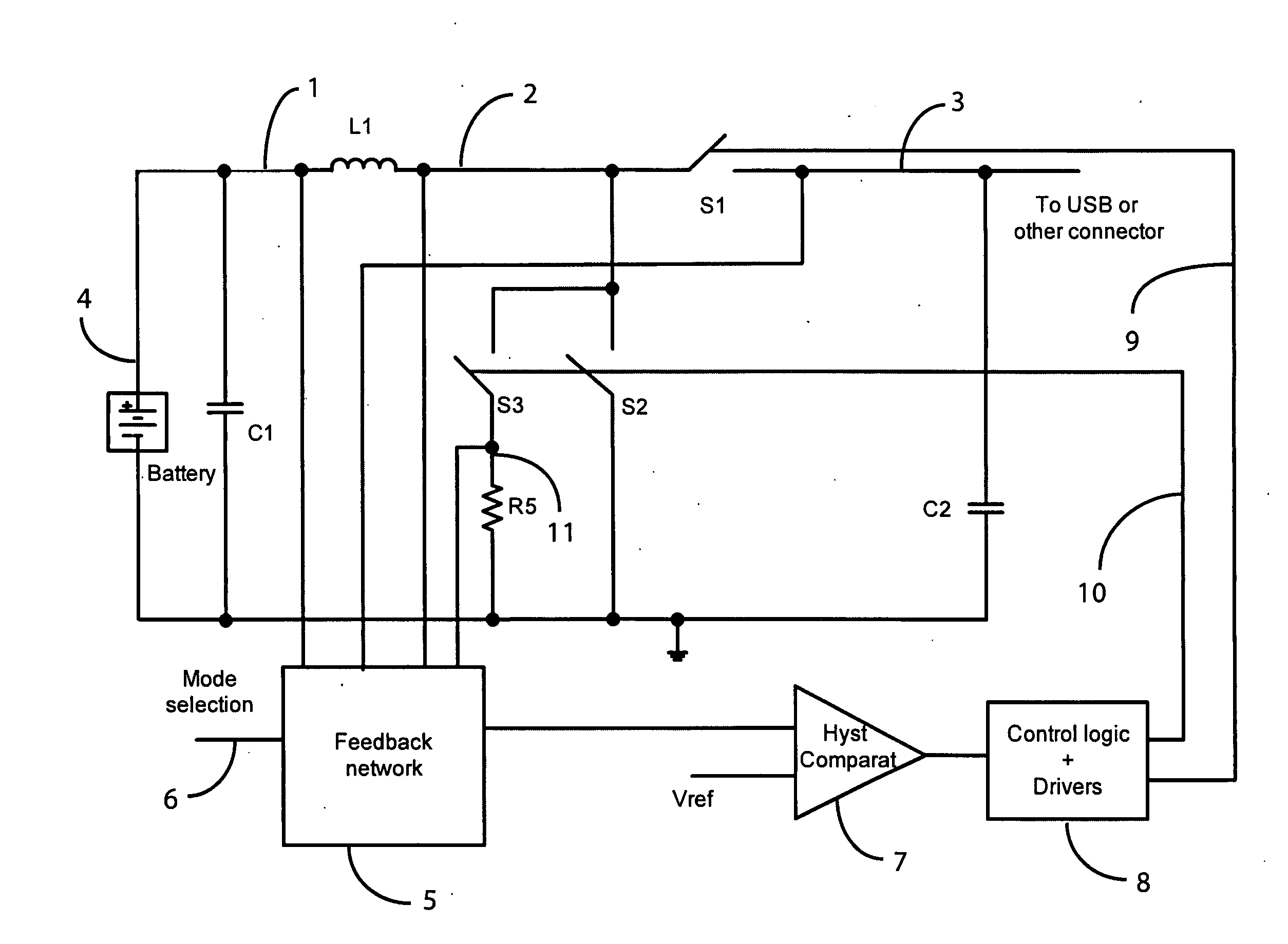
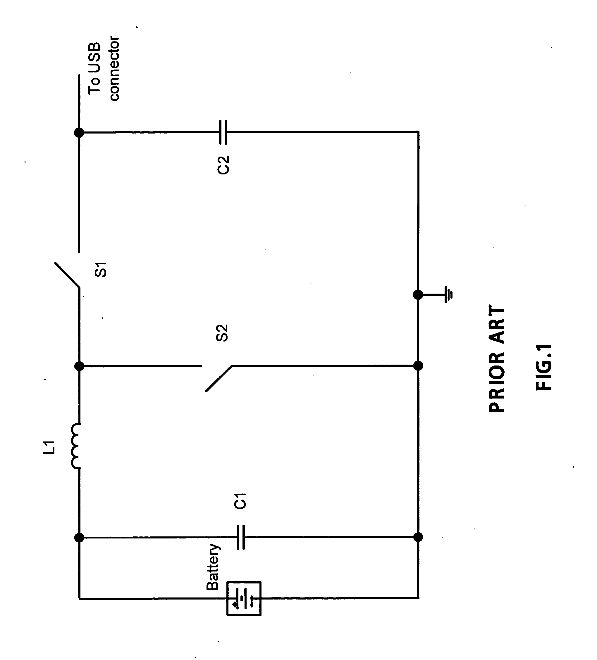
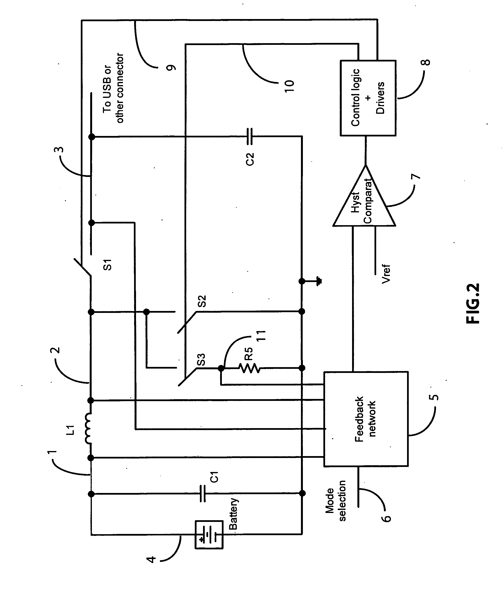
[0059]The present invention, in the embodiment shown in FIG. 2, describes a bidirectional power converter that, when the current in the inductor L1 flows from left to right, that is from the node 1 to the node 2, operates as a boost regulating the voltage at the node 3 to be higher than the voltage of the battery 4 on the left side of the schematic. When the current in the inductor L1 flows from right to left, that is from the node 2 to the node 1, the converter operates as a buck regulating the current or the voltage of the battery starting from a higher voltage at the node 3.

[0060]The switch S1 represents the high side power transistor, and generally is switched in opposition of phase with respect to the switch S2 that represents the low side power transistor. The switch S3 operates substantially in phase with the switch S2 and its main purpose is to sense the voltage of the switching node 2 when the low side is turned on and to report it to the positive terminal of the re...


PUM


Abstract

A novel switching hysteretic bidirectional power converter is presented. The converter includes the generation of a synthetic ripple signal and feedback networks to hysteretically control the power converter both when the converter operates as a boost converter with the flow of power in one direction, and when the converter operates as a buck power converter with the flow of power in the opposite direction.
The presented approach provides a switching converter with a much simpler control method with respect to conventional inductive bidirectional power converters. The hysteretic control provides stable operation in all conditions with excellent load and line transient response. Furthermore this allows the operation of the bidirectional power converter with much higher switching frequencies with respect to state of the art conventional approaches, thus reducing the cost and size of the passive components storing energy during the conversion.
Since bidirectional switching power converters are used mainly when the flow of power is bidirectional, the typical application involves the charging and discharging of batteries, and as part of this novel approach, an hysteretic battery charger including hysteretic constant current and constant voltage control is introduced as part of a larger bidirectional switching power converter.

Description


Claims


Application Information

Patent Timeline
Owner QUALCOMM INC
Learn More