Compact smart antenna for mobile wireless communications

a mobile wireless communication and antenna technology, applied in the field of smart antennas, can solve the problems of not being suitable for real time, affecting the performance of the antenna array, and only seeing limited commercial use, so as to achieve high throughput, facilitate long-range communication, and suppress interference and jamming

Inactive Publication Date: 2012-11-29
MONTANA STATE UNIVERSITY +1
View PDF7 Cites 55 Cited by
  • Summary
  • Abstract
  • Description
  • Claims
  • Application Information

AI Technical Summary

Benefits of technology

[0009]In one embodiment, a compact, high gain 8-element circular smart antenna is able to scan a beam azimuthally through 360°. The 8-element array is placed on a ground skirt and connected to an 8-channel beamforning board via a transfer plate. Each channel has two T/R switches, one band pass filer, one power amplifier, two low noise amplifiers, one phase shifter, and one attenuator. The 8-channel-signal is combined through power splitters/combiners and then sent to a connected radio. An FPGA...

Problems solved by technology

Smart antennas were initially developed during WWII for military use but have seen only limited commercial use due to high costs and large electronic processing delays.
Adaptive arrays may inclu...

Method used


Image

  • Compact smart antenna for mobile wireless communications
  • Compact smart antenna for mobile wireless communications
  • Compact smart antenna for mobile wireless communications

Examples


Embodiment Construction

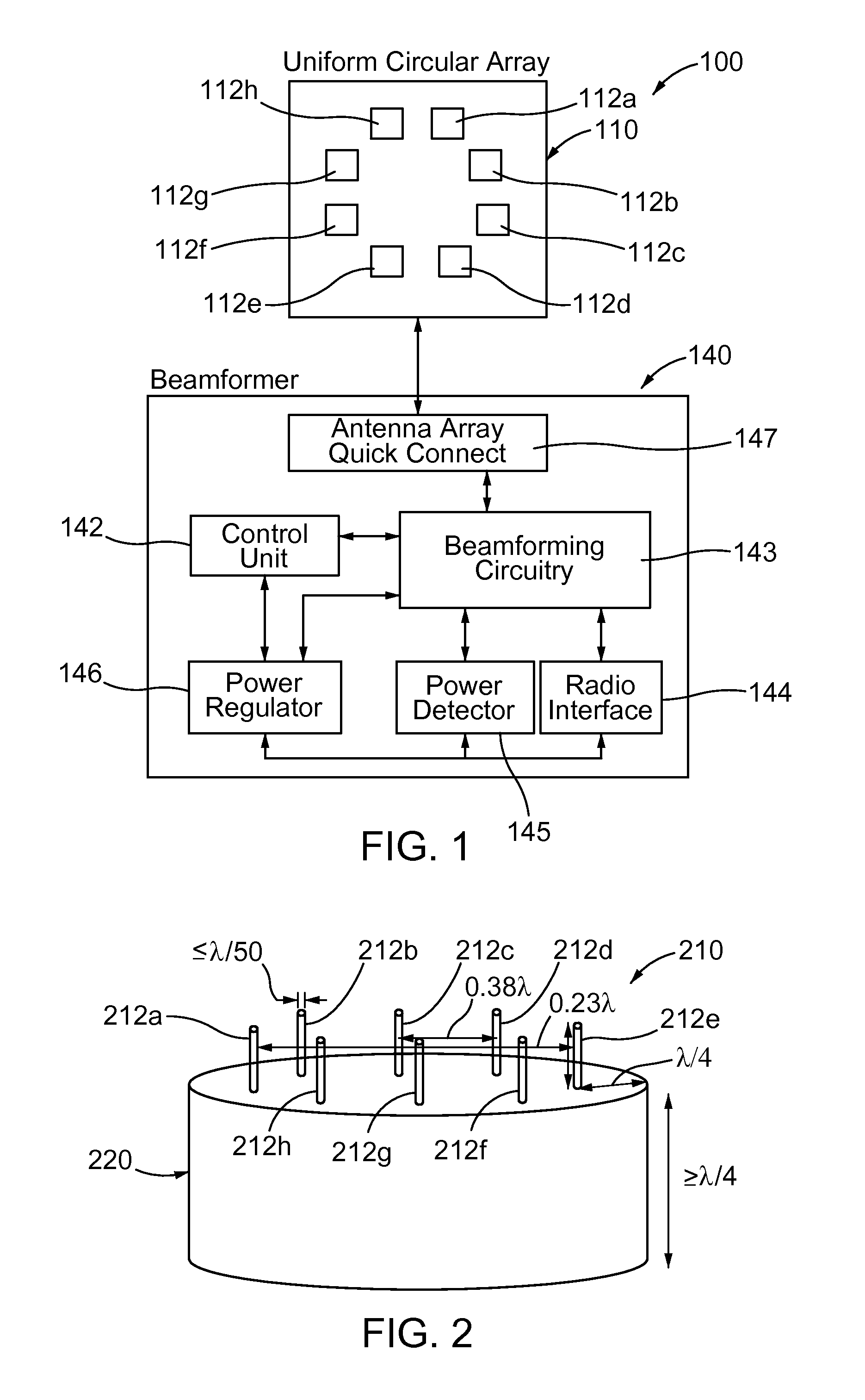
[0020]Methods and apparatus for a compact smart antenna are described herein. In one embodiment, the smart antenna contains an array head, a beamformer and a power supply. The array head can be an 8-element array on a ground skirt. The smart antenna can operate, for example, at a frequency of 5.8 GHz with bandwidth of 200 MHz. It should be understood that the 5.8 GHz frequency is illustrative and that the smart antenna can operate at any selected frequency.

[0021]The smart antenna can include a beamformer, which can be a digitally-controlled phased analog array system. An on-board FPGA (with or without an external computer) can be included and can automatically perform tasks such as target searching, beamforming and tracking, as described in more detain herein.

[0022]The software for the FPGA establishes and maintains a communication link between the beamformer (e.g., the digitally-controlled phased analog array system) coupled to the smart antenna and a radio located at some distance...


PUM


Abstract

A compact, high gain 8-element circular smart antenna is able to scan a beam azimuthally through 360°. The 8-element array is placed on a ground skirt and connected to an 8-channel beamforning board via a transfer plate. Each channel has two T/R switches, one band pass filer, one power amplifier, two low noise amplifiers, one phase shifter, and one attenuator. The 8-channel-signal is combined through power splitters/combiners and then sent to a connected radio. An FPGA chip controls the digital phase shifters, attenuators and switches for signal searching, beamforming and tracking. The smart antenna can be operated as a compact switched beam system or with an additional processor as an adaptive array system. The smart antenna is capable of tracking mobile targets, directionally communicating with desired users, suppressing interference and jamming, and enabling long range communications with high throughput and reliable connection because of its high antenna gain.

Description

RELATED APPLICATION[0001]This application is a continuation of International Application No. PCT / U.S. 2010 / 056207, filed Nov. 10, 2010, entitled “Compact Smart Antenna for Mobile Wireless Communications,” which claims priority to U.S. Patent Provisional Application No. 61 / 259,909, filed Nov. 10, 2009, entitled “Compact Smart Antenna for Mobile Wireless Communications”; each of which is incorporated herein by reference in their entireties.GOVERNMENT RIGHTS STATEMENT[0002]This invention was made with government support under grant number N66001-08-D-0116 awarded by the Navy and grant number 0519403 awarded by the National Science Foundation. The government has certain rights in the invention.BACKGROUND[0003]This invention relates to smart antennas, such as for example, high gain smart antennas suitable for a mobile or fixed relay node for wireless communications over long distances.[0004]Smart antennas were initially developed during WWII for military use but have seen only limited co...

Claims


Application Information

Patent Timeline
IPC IPC(8): G01S13/06H01Q3/12
CPCH01Q3/24H04B7/088H01Q21/205H01Q21/20
Inventor HUANG, YIKUNOLSON, ANDYTIDD, WILL G.TRAXINGER, AARON S.WOLFF, RICHARD
Owner MONTANA STATE UNIVERSITY
Why Eureka
Try Eureka