Electrostatic protection component

a technology of electrostatic protection and components, applied in the direction of shielding materials, structural fixed capacitor combinations, relays, etc., can solve the problems of reducing the inability to increase the durability of the electrostatic protection component, and the electrode to be separated, so as to increase the size of the space region in the vicinity of the discharge portion, increase the durability of the electrostatic protection component, and reduce the clamp voltage

Active Publication Date: 2012-11-29
TDK CORPARATION
View PDF3 Cites 25 Cited by
  • Summary
  • Abstract
  • Description
  • Claims
  • Application Information

AI Technical Summary

Benefits of technology

[0026]In the electrostatic protection component according to the third aspect of the present invention, the hollow portion is adjacent to and in contact with the discharge-inducing portion in the gap. In this case, breakdown by discharge can be induced in the horizontal direction, and thus it is possible to suppress breakdown by discharge in the thickness direction (the lamination direction of the ceramic layer) of the discharge-inducing portion. Since the breakdown in the thickness direction of the discharge-inducing portion can be suppressed in this way, with the electrostatic protection component according to the third aspect of the present invention, the limitation of the number of times of discharge and variations in the discharge start voltage are also suppressed, with the result that it is possible to enhance the durability of the electrostatic protection component.
[0027]In the electrostatic protection component according to the third aspect of the present invention, the hollow portion is formed so as to be overlapped on the discharge-inducing portion. In this case, there can be increased the size of a space region (the thickness in the lamination direction) in the vicinity of the discharge portions in which discharge is more likely to occur in the discharge-inducing portions. By the fact that the size of the space region in the vicinity of the discharge portions can be increased, with the electrostatic protection component according to the third aspect of the present invention, it becomes possible to reduce the clamp voltage.
[0028]In the electrostatic protection component according to the third aspect of the present invention, the first discharge electrode may include a first side edge which extends in a first direction and which extends along the first direction, the second discharge electrode may include a second side edge which extends in the first direction and which extends al

Problems solved by technology

Therefore, even if the portions of the discharge electrodes facing each other are lengthened, since the discharge portion is approximately limited to the regions of the tips, there has been a problem in which the durability of an electrostatic protection component cannot be increased (a first problem).
Therefore, in the electrostatic protection component described above, when the hollow portion is formed by the dissipation of a hollow portion-forming lacquer at the time of firing, the tip of the discharge electrode becomes free within the hollow portion, and thus there is a possibility that the difference in contraction between the discharge electrode and a body causes the discharge electrode to be separated fro

Method used


Image

  • Electrostatic protection component
  • Electrostatic protection component
  • Electrostatic protection component

Examples


first embodiment

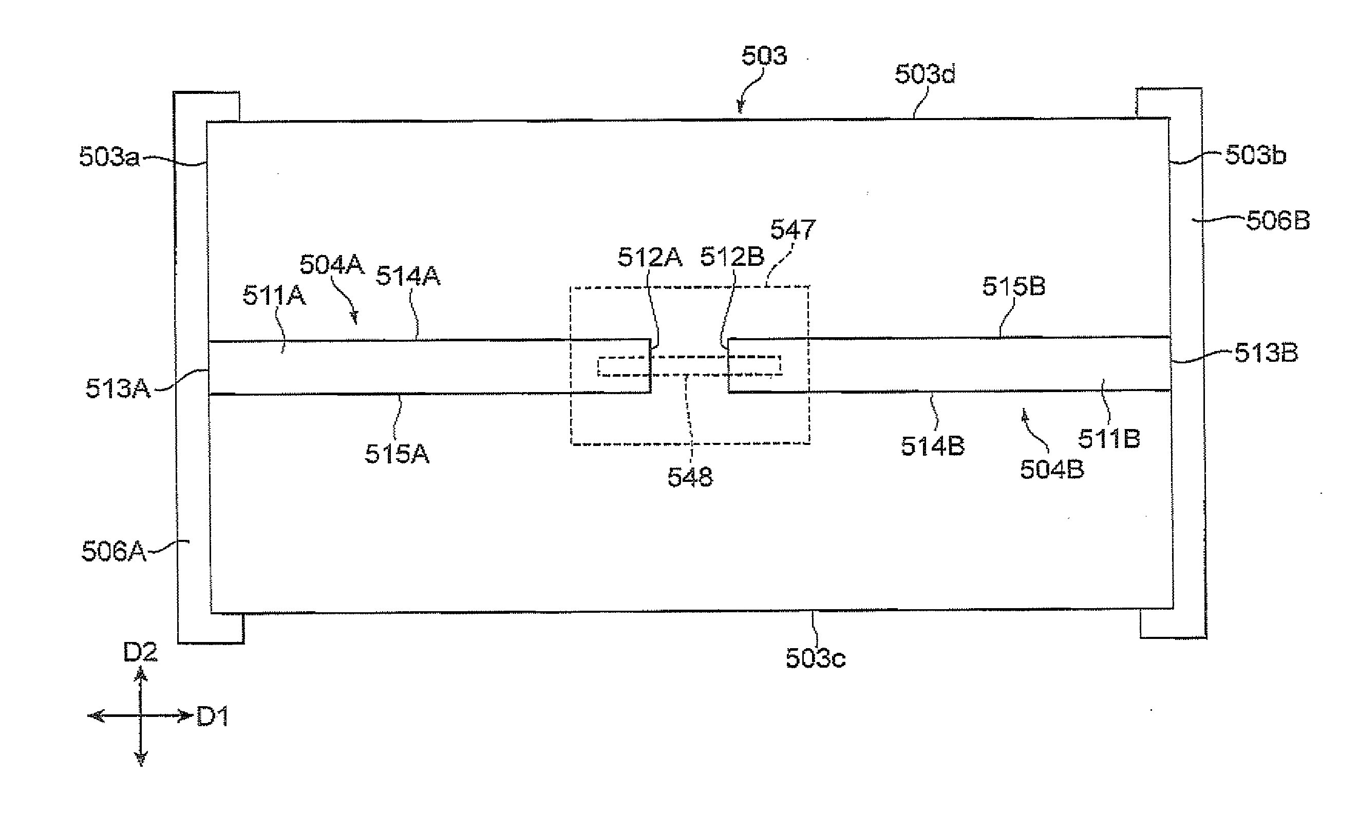
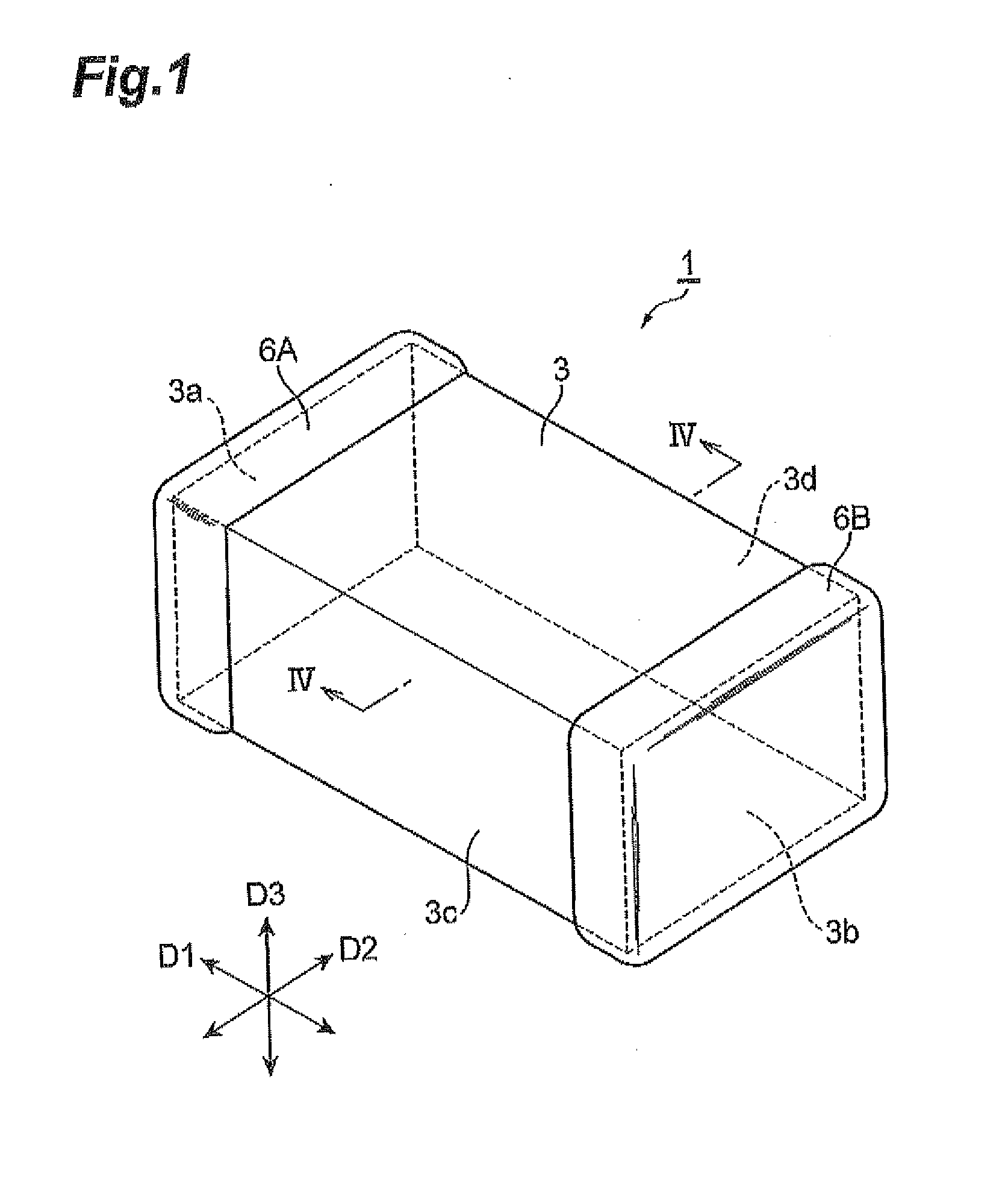
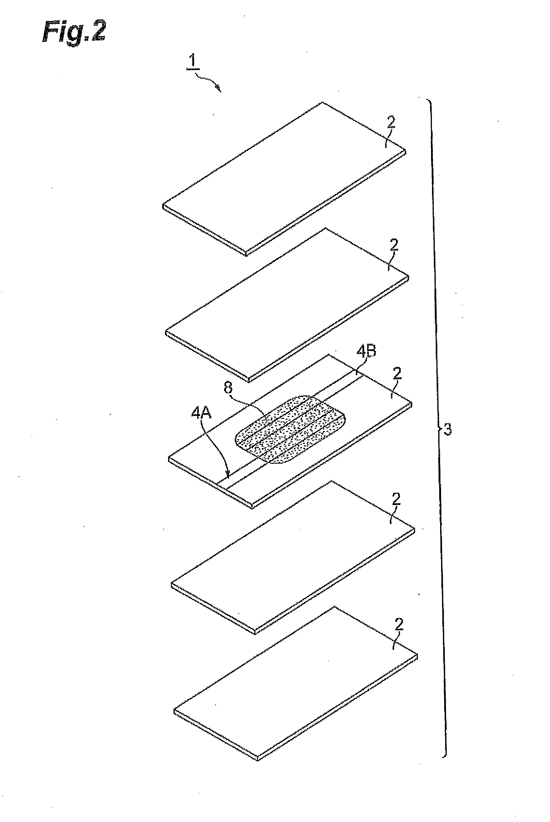
[0080]FIG. 1 is a perspective view of an electrostatic protection component according to a first embodiment. FIG. 2 is a developed perspective view of a body of the electrostatic protection component according to the first embodiment. FIG. 3 is a diagram of a discharge portion of the electrostatic protection component when viewed in a direction of lamination. In FIG. 3, ceramic substrates 2 that are placed by one sheet on discharge electrodes 4A and 4B are shown being omitted. FIG. 4 is an enlarged cross-sectional view of the discharge portion taken along line IV-IV shown in FIG. 1. In the following description, a direction in which the body 3 extends is referred to as a longitudinal direction D1, a direction perpendicular to the longitudinal direction D1 in a direction of a flat surface of the ceramic substrates 2 is referred to as a short direction D2 and a direction in which the ceramic substrates 2 are laminated is referred to as a lamination direction D3.

[0081]The electrostatic...

second embodiment

[0140]FIG. 16 is a perspective view of an electrostatic protection component according to a second embodiment. FIG. 17 is a developed perspective view of a body of the electrostatic protection component according to the second embodiment. FIG. 18 is a plan view of a discharge portion of the electrostatic protection component when viewed in a direction of lamination. In FIG. 18, ceramic layers 402 on first and second discharge electrodes 404A and 404B and the like are omitted. FIG. 19(a) is a diagram for illustrating a cross-sectional configuration taken along line XIXa-XIXa shown in FIG. 18; FIG. 19(b) is a diagram for illustrating a cross-sectional configuration taken along line XIXb-XIXb shown in FIG. 18. FIG. 20 is a diagram for illustrating a cross-sectional configuration taken along line XX-XX shown in FIG. 16. In the following description, a direction in which a body 403 extends is referred to as the longitudinal direction D1, a direction perpendicular to the longitudinal dire...

third embodiment

[0183]An electrostatic protection component 401a according to a third embodiment will now be described with reference to FIGS. 25 and 26. As in the second embodiment, the electrostatic protection component 401a according to the present embodiment includes the body 403, the discharge electrodes 404A and 404B and the external electrodes 406A and 406B; the electrostatic protection component 401a differs from that of the second embodiment in that the electrostatic protection component 401a includes one discharge-inducing portion 438 and a hollow portion 437 formed on the discharge-inducing portion 438.

[0184]The discharge-inducing portion 438 is approximately rectangular as viewed in the lamination direction D3, and has the function of connecting the first and second discharge electrodes 404A and 404B to facilitate the occurrence of discharge between the first and second discharge electrodes 404A and 404B. The discharge-inducing portion 438 is formed so as to contact an approximate centr...


PUM


Abstract

An electrostatic protection component includes: a body in which a plurality of ceramic substrates is laminated; and a pair of discharge electrodes which are formed within the body and which are spaced to face each other. The discharge electrodes include main body portions extending along a longitudinal direction, and the main body portions include tips in the longitudinal direction and side edges extending along the longitudinal direction. The pair of discharge electrodes are arranged such that both the main body portions are adjacent to each other in a short direction. The discharge electrodes face each other in the short direction between the side edges, and discharge occurs only between the side edges, between the discharge electrodes.

Description

BACKGROUND OF THE INVENTION[0001]1. Field of the Invention[0002]The present invention relates to an electrostatic protection component that protects an electronic device from ESD.[0003]2. Related Background of the Invention[0004]ESD (electro-static discharge) is a phenomenon in which, when a charged conductor (such as a human body) contacts another conductor (such as an electronic device) or sufficiently approaches it, an intense discharge is generated. The ESD causes problems such as damages and malfunctions of electronic devices. In order to solve these problems, it is necessary to prevent an excessively high voltage generated at the time of discharge from being applied to a circuit of electronic devices. An electronic component used for this type of application is an electrostatic protection component, and is also referred to as a surge absorbing element or a surge absorber.[0005]In an electrostatic protection component disclosed in Japanese Patent No. 4247581 or Japanese Patent ...

Claims


Application Information

Patent Timeline
IPC IPC(8): H05F3/00
CPCH05K9/0067H05F3/04H01G4/40H01T4/12H05K9/0079H01T2/00H01T4/10
Inventor UMEDA, HIDENOBUYOSHINO, MAKOTOSATO, TAKAHIROHATTORI, TAKUOSATO, SHINICHISHIBAYAMA, TAKESHI
Owner TDK CORPARATION
Why Eureka
Try Eureka