Thin film-manufacturing apparatus,thin film-manufacturing method,and substrate-conveying roller

a technology of thin film and manufacturing apparatus, which is applied in the direction of manufacturing tools, web handling, transportation and packaging, etc., can solve the problems of inability to use such a large amount of cooling gas directly removing heat, thermal load during film formation, etc., and achieve the effect of suppressing the vacuum reduction and high gas pressure between the first shell and the substra

Active Publication Date: 2012-11-29
PANASONIC INTELLECTUAL PROPERTY MANAGEMENT CO LTD
View PDF11 Cites 22 Cited by
  • Summary
  • Abstract
  • Description
  • Claims
  • Application Information

AI Technical Summary

Benefits of technology

[0020]According to the present invention, cooling gas can be fed efficiently into the gap between the first shell and the substrate. Therefore, even if a reduced amount of cooling gas is introduced, the gas pressure between the first she

Problems solved by technology

There are problems of thermal load during film formation and cooling of the substrate as factors that determine the success or failure of the continuous thin film pro

Method used


Image

  • Thin film-manufacturing apparatus,thin film-manufacturing method,and substrate-conveying roller
  • Thin film-manufacturing apparatus,thin film-manufacturing method,and substrate-conveying roller
  • Thin film-manufacturing apparatus,thin film-manufacturing method,and substrate-conveying roller

Examples


Embodiment Construction

[0036]Hereinafter, an embodiment of the present invention is described with reference to the drawings.

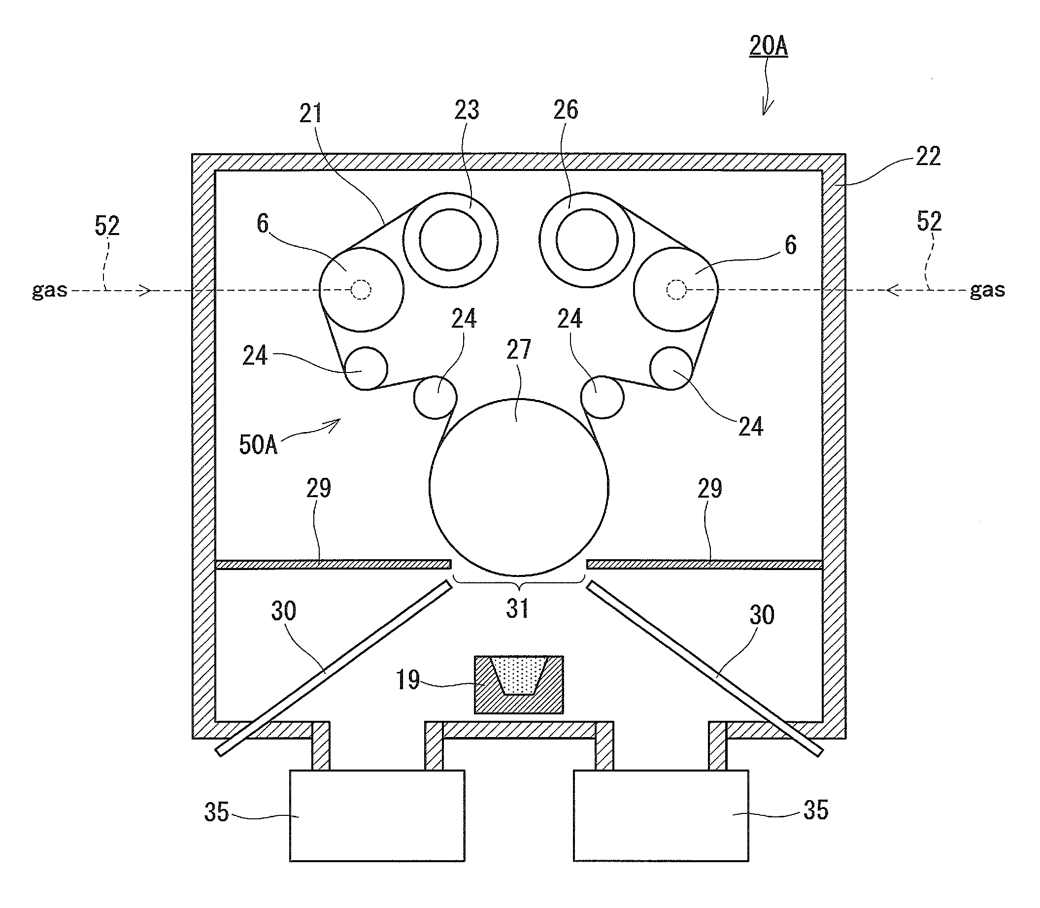
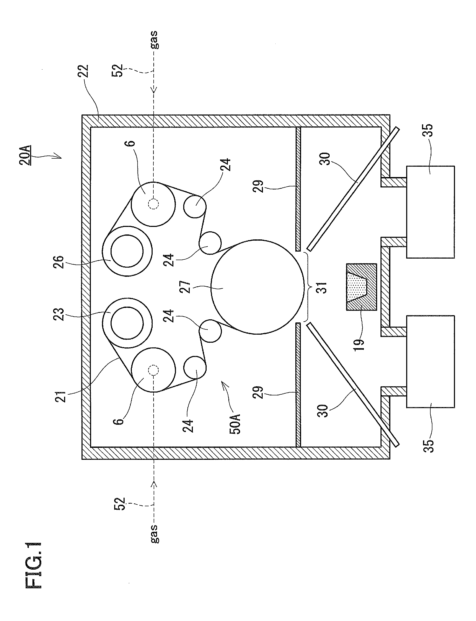
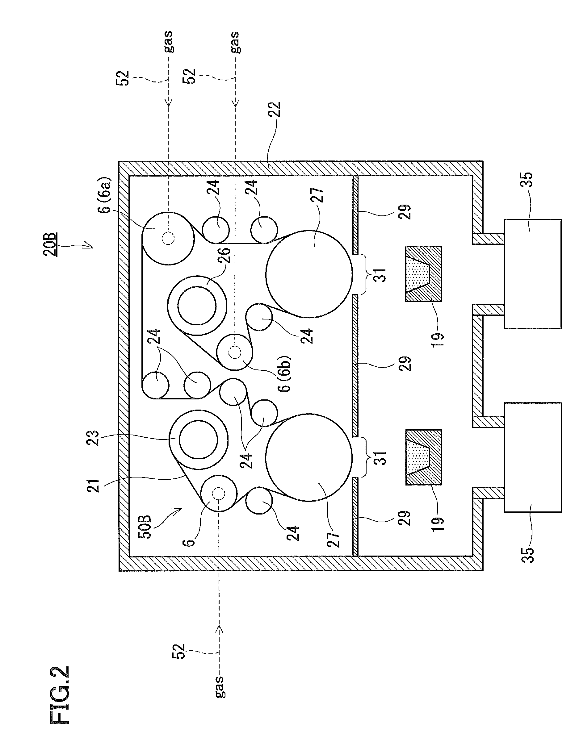
[0037]FIG. 1 schematically shows an example of the overall configuration of a film-forming apparatus. A film-forming apparatus 20A (thin film-manufacturing apparatus) includes a vacuum chamber 22, a conveyance system 50A, a film-forming source 19, a shield plate 29, raw material gas introduction tubes 30, and discharge pumps 35. The conveyance system 50A is composed of a spool roller 23, blowing rollers 6, conveying rollers 24, a can 27, and a spool roller 26. Each blowing roller 6 has a function of conveying a substrate 21 and a function of supplying a gas for cooling the substrate 21 toward the substrate 21. The blowing roller 6 is one of conveying rollers. A gas is supplied from the outside of the vacuum chamber 22 to the blowing rollers 6 through gas supply pipes 52.

[0038]The vacuum chamber 22 is a pressure-resistant container member having an internal space. The conveyance syst...


PUM

PropertyMeasurementUnit
Angleaaaaaaaaaa
Angleaaaaaaaaaa
Flow rateaaaaaaaaaa

Abstract

A conveyance system 50A of a film-forming apparatus 20A includes a blowing roller 6 having a function of supplying a cooling gas toward a substrate 21. The blowing roller has the first shell 11 and the internal block 12. The first shell 11 has a plurality of first through holes 13 as a gas supply channel, and is rotatable in synchronization with the substrate 21. The internal block 12 is disposed inside the first shell 11. A manifold 14 is defined by the internal block 12 inside the first shell 11. The manifold 14 is formed so as to introduce the gas toward the plurality of first through holes 13 within the range of a holding angle. A clearance 15 facing the plurality of first through holes 13 outside the range of the holding angle is further formed inside the first shell 11. In the radial direction, the manifold 14 has a relatively large dimension, and the clearance 15 has a relatively small dimension.

Description

TECHNICAL FIELD[0001]The present invention relates to a thin film-manufacturing apparatus, a thin film-manufacturing method, and a substrate-conveying roller.BACKGROUND ART[0002]Thin film techniques are widely developed for miniaturization and performance enhancement of devices. Devices in the form of a thin film not only provides a direct advantage for users but also plays an important role from an environmental viewpoint, for example, in conserving the earth resources or reducing power consumption.[0003]For such development in thin film techniques, it is indispensable to satisfy requirements in view of industrial availability such as efficiency enhancement, stabilization, productivity enhancement, and cost reduction in the thin film-manufacturing method, for the purpose of which efforts have been continuously made.[0004]In order to enhance the productivity of thin films, film-forming techniques at high deposition rates are essential. In thin film-manufacturing methods such as vacu...

Claims


Application Information

Patent Timeline
IPC IPC(8): C23C16/458B65H20/02
CPCC23C14/30C23C14/562C23C14/541C23C14/564C23C16/466C23C16/545
Inventor HONDA, KAZUYOSHISHIBUTANI, SATOSHISHINOKAWA, YASUHARUOKAZAKI, SADAYUKIUCHIDA, NORIYUKIAMO, NORIAKI
Owner PANASONIC INTELLECTUAL PROPERTY MANAGEMENT CO LTD
Why Eureka
Try Eureka