
Method of producing light- emitting device and light-emitting device

Active Publication Date: 2012-11-29
CITIZEN WATCH CO LTD +1
View PDF0 Cites 105 Cited by
  • Summary
  • Abstract
  • Description
  • Claims
  • Application Information

AI Technical Summary

Benefits of technology

[0022]According to the method of producing a light-emitting device of the present invention, the adhesive sheet is stripped from the sealing member to expose the element electrodes in a pair of the light-emitting element from one surface of the sealing member. Accordingly, the external connection electrodes in a pair configured to be electrically connected to the element electrodes can be formed on this surface of the sealing member. This made it possible to produce a light-emitting device quite easily that does not use a substrate on which a light-emitting element is to be mounted and external connection electrodes are to be formed.

Problems solved by technology

Accordingly, this substrate becomes an obstacle to reduce thickness of the light-emitting device 100 or 200 and a cause for deterioration of heat dissipation properties.
Further, this substrate increases the number of components, and it also becomes a cause for increase in cost.
This stripping is performed by mechanical or chemical process, making removal of the substrate 302 difficult work and lowering efficiency in this work.
An additional problem also occurs in that it is hard to maintain the quality of the light-emitting device 300 at a constant level from which the substrate 302 has been stripped.

Method used


Image

  • Method of producing light- emitting device and light-emitting device
  • Method of producing light- emitting device and light-emitting device
  • Method of producing light- emitting device and light-emitting device

Examples


first embodiment

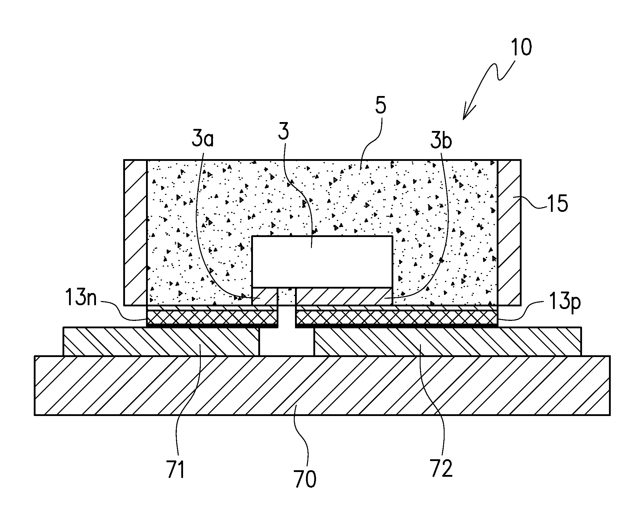
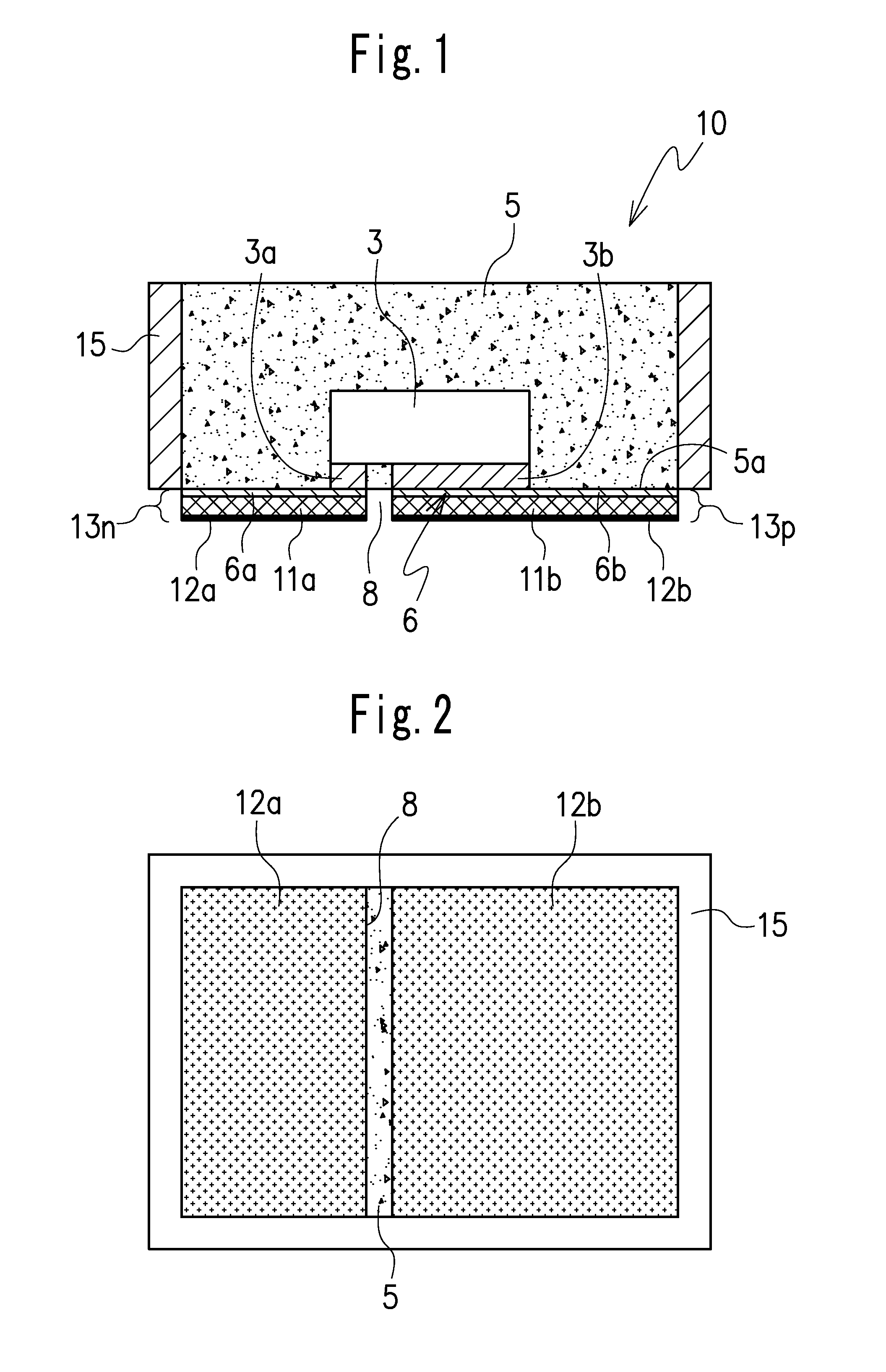
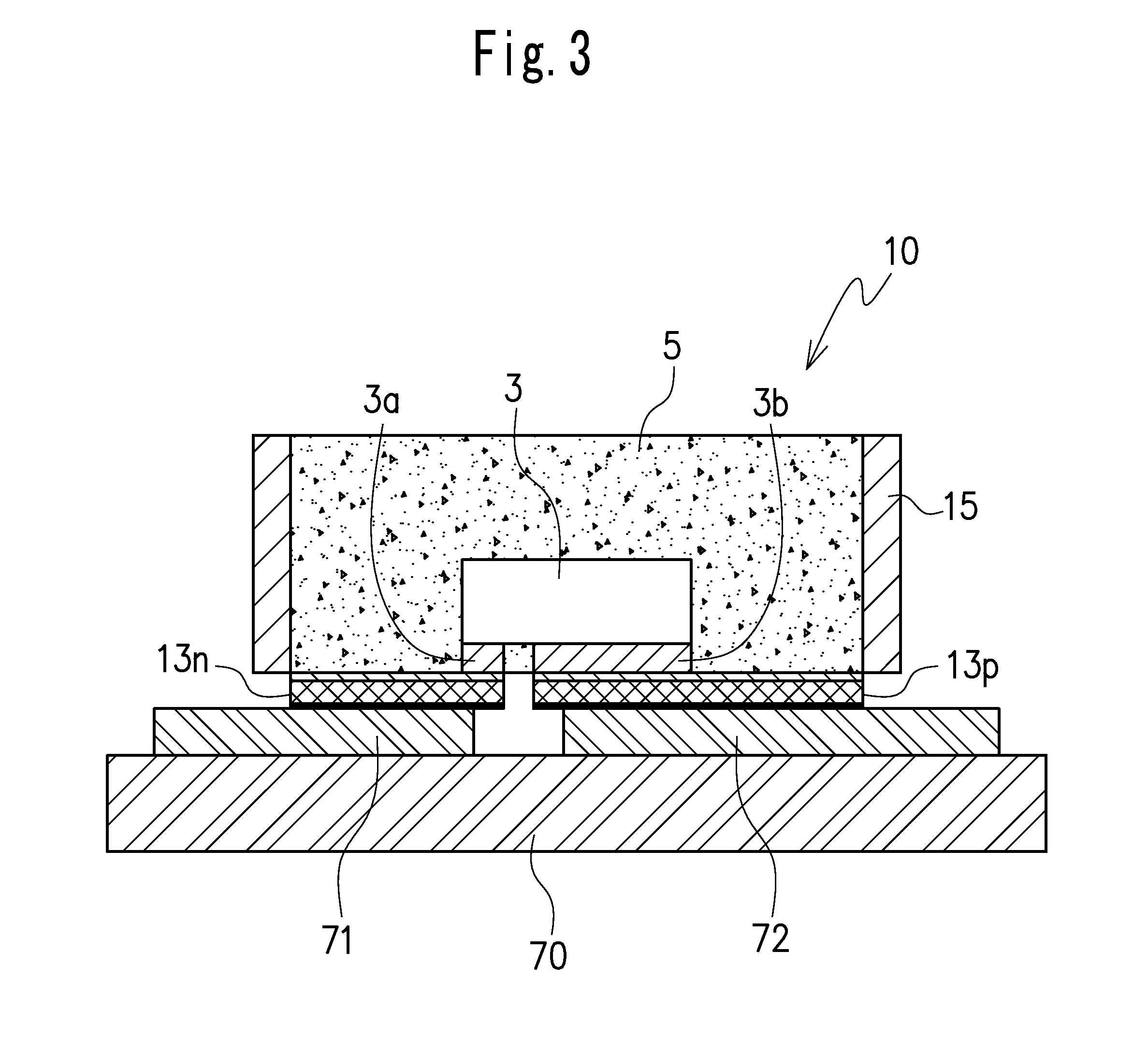
[0068]FIGS. 1 to 3 show a light-emitting device produced by a production method according to a first embodiment of the invention. FIGS. 4 to 25 show steps of the production method according to the first embodiment.

[0069]A light-emitting device 10 shown in FIGS. 1 and 2 includes a light-emitting diode element (hereinafter called light-emitting element) 3 including an N electrode 3a and a P electrode 3b being element electrodes in a pair, a transparent sealing resin 5 or a light-transmitting sealing resin 5 in which fluorescent particles are mixed (hereinafter called sealing member) sealing the light-emitting element 3 while a lower surface being at least one surface of each of the element electrodes in a pair of the light-emitting element 3 is exposed, and external connection electrodes in a pair each formed on at least one surface of one of the element electrodes in a pair exposed from the sealing member 5, the external connection electrodes being electrically connected to the N ele...

second embodiment

[0087]FIG. 26 shows a light-emitting device produced by a production method according to a second embodiment of the present invention. FIGS. 27 to 32 show steps of the production method according to the second embodiment.

[0088]A light-emitting device 20 according to the present embodiment has the same basic structures as those of the light-emitting device 10 according to the first embodiment shown in FIG. 1. Accordingly, the same structures are identified by the same reference numbers, and will not be described in detail.

[0089]The structure of the light-emitting device 20 is different from that of the previously described light-emitting device 10 in that a protection film 25 is formed on a substantially entire lower surface 5a of a sealing member 5 resin-sealing a light-emitting element 3. The protection film 25 is formed with the intent of reinforcing the flexible sealing member 5 made of a silicone resin. The protection film 25 is capable of stabilizing an N external connection el...

third embodiment

[0103]FIG. 33 shows a light-emitting device obtained by a production method according to a third embodiment of the invention. FIG. 34 shows characteristic steps of the production method according to the third embodiment. Members corresponding to those of the first embodiment are denoted by the same reference numbers, and will not be described in detail.

[0104]As shown in FIG. 33, a light-emitting device 30 of the third embodiment includes: a light-emitting element 3 including an upper surface, a lower surface, a peripheral surface extending between the upper and lower surfaces, and element electrodes in a pair formed on the lower surface; a sealing member sealing the light-emitting element 3 and arranged so as to expose the element electrodes in a pair of the light-emitting element 3; and external connection electrodes in a pair electrically connected to the element electrodes in a pair of the light-emitting element 3 and provided on the sealing member. The sealing member includes a ...


PUM


Abstract

It is an object to produce a thin light-emitting device in an extremely simple method that does not include a substrate on which a light-emitting element is to be mounted.A method of producing a light-emitting device, including: preparing a plurality of light-emitting elements each including element electrodes in a pair; arranging the plurality of light-emitting elements in a sealing member to expose at least one surface of each of the element electrodes in a pair provided to each of the light-emitting elements; forming external connection electrodes in a plurality of pairs on the sealing member, the external connection electrodes in each pair being electrically connected to the element electrodes in a pair provided to each of the light-emitting elements; and obtaining a plurality of light-emitting devices by dividing the sealing member with the plurality of light-emitting elements, the light-emitting devices each including a light-emitting element having element electrodes in a pair, a sealing member sealing the light-emitting element while at least one surface of each of the element electrodes in a pair is exposed, and external connection electrodes in a pair provided on the sealing member and electrically connected to the element electrodes in a pair.

Description

TECHNICAL FIELD[0001]The present invention relates to a method of producing a light-emitting device including a light-emitting diode element and the light-emitting device.BACKGROUND ART[0002]A light-emitting diode element (hereinafter called light-emitting element briefly) has a compact size, provides favorable light-emitting efficiency and vivid color, of emission and has long operating life and excellent driving characteristics and the like. Accordingly, in recent years, it has been widely used as a light source for backlight of a color display device and for illumination purposes, for example. Thus, in embodiments, a light-emitting device including a light-emitting element will be described as the light-emitting device of the present invention.[0003]A light-emitting device for emitting white light or a light-emitting device for emitting colored light has been proposed in recent years, and in this device, a light-emitting element mounted on a substrate is covered with a sealing me...

Claims


Application Information

Patent Timeline
IPC IPC(8): H05B33/10
CPCH01L33/486H01L33/52H01L33/60H01L2933/0033H01L2933/0066H01L2224/32013H01L2224/48227H01L2224/48465H01L2224/73265H01L2224/16225H01L2224/48091H01L2924/00014H01L2924/00H01L2224/19H01L2924/181H01L2224/96H01L2224/97H01L21/568H01L2224/04105H01L2224/32225H01L2224/73267H01L2924/00012H01L2224/83
Inventor IMAZU, KENJI
Owner CITIZEN WATCH CO LTD
Learn More