Electric linear motion actuator and electric disk brake system

a technology of actuators and actuators, applied in mechanical energy handling, mechanical equipment, mechanical energy handling, etc., can solve the problems of actuators being large in size and the inability of the actuator to increase the power to the extent required in the electric disk brake system, and achieve the effect of reducing contact pressure and easy and accurate formation

Active Publication Date: 2012-12-06
NTN CORP
View PDF8 Cites 3 Cited by
  • Summary
  • Abstract
  • Description
  • Claims
  • Application Information

AI Technical Summary

Benefits of technology

[0034]Preferably, the side surfaces are inclined at an angle equal to an angle of inclination of the side walls such that the side surfaces of the helical rib are uniformly brought into contact with the side walls of the circumferential or helical grooves when the helical rib is engaged in the grooves, thereby allowing the helical rib to be smoothly and reliably engaged in the circumferential or helical grooves.
[0035]At least either the side surfaces or the side walls may be curved surfaces which are convex in a direction in which the respective side surfaces or the side walls are inclined. This prevents the side walls of the helical rib from contacting the side walls of the circumferential grooves or helical grooves at their portions near their roots or apexes when the helical rib is engaged in the circumferential or helical grooves.
[0036]The curved surfaces are preferably arcuate surfaces because arcuate surfaces can be formed easily and accurately.
[0037]Such arcuate surfaces preferably have a radius of curvature larger than a height of the helical rib so that the side surfaces of the helical rib contact the side walls of the circumferential or helical grooves over a larger area, thereby reducing the contact pressure.

Problems solved by technology

But these mechanisms cannot increase power to an extent required in an electric disk brake system.
Such actuators tend to be large in size because they include an additional speed reducer.

Method used


Image

  • Electric linear motion actuator and electric disk brake system
  • Electric linear motion actuator and electric disk brake system
  • Electric linear motion actuator and electric disk brake system

Examples


Embodiment Construction

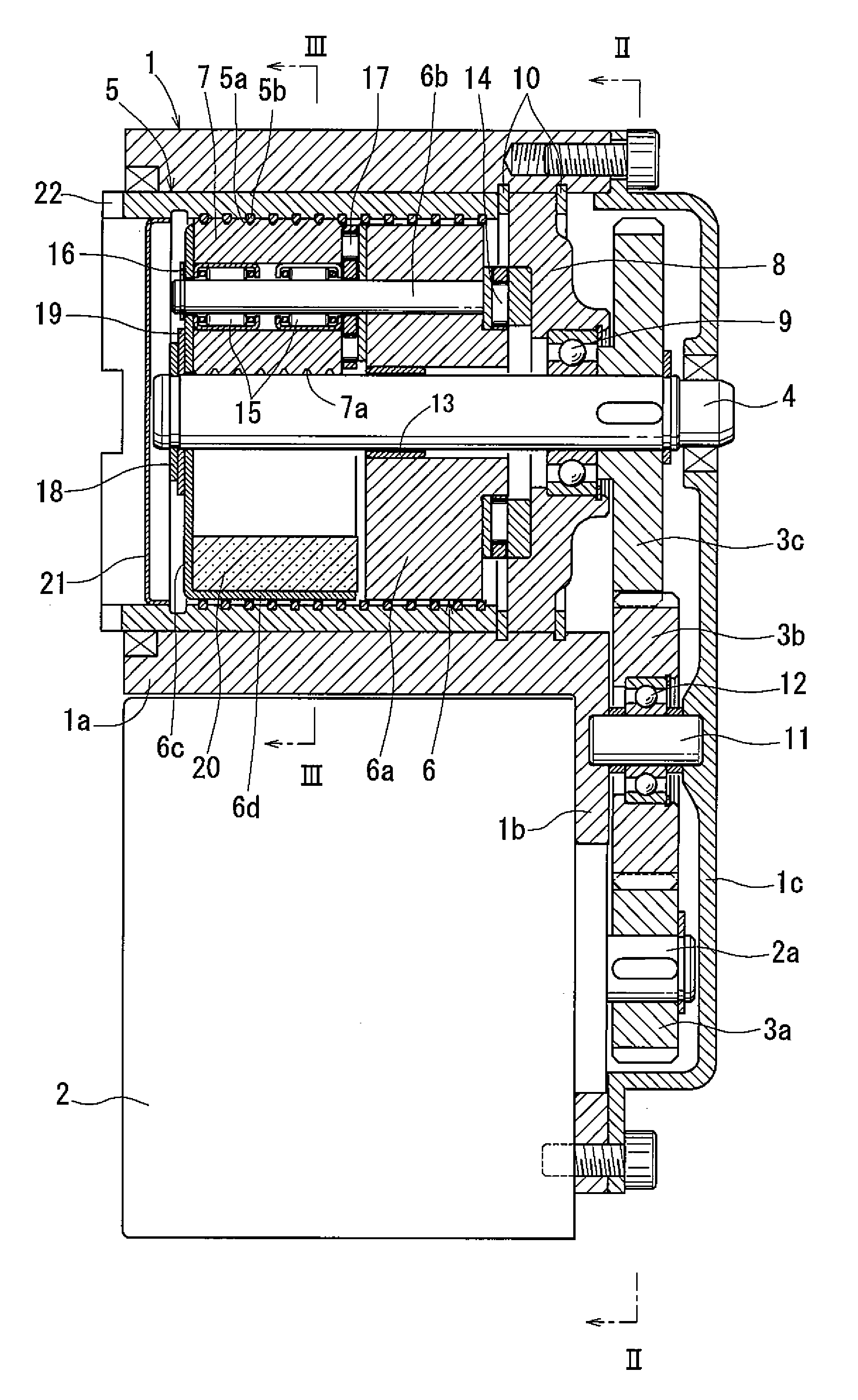
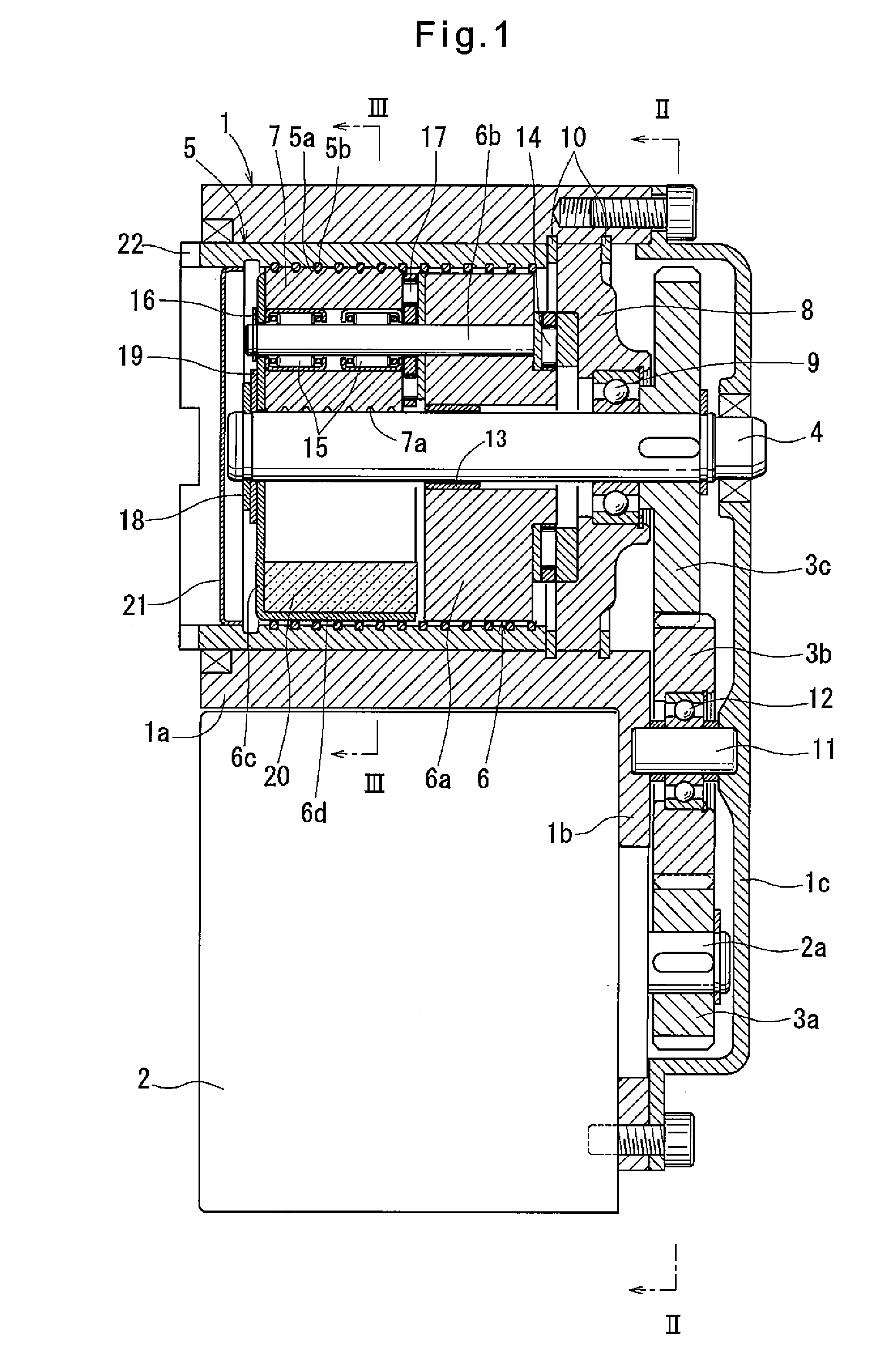
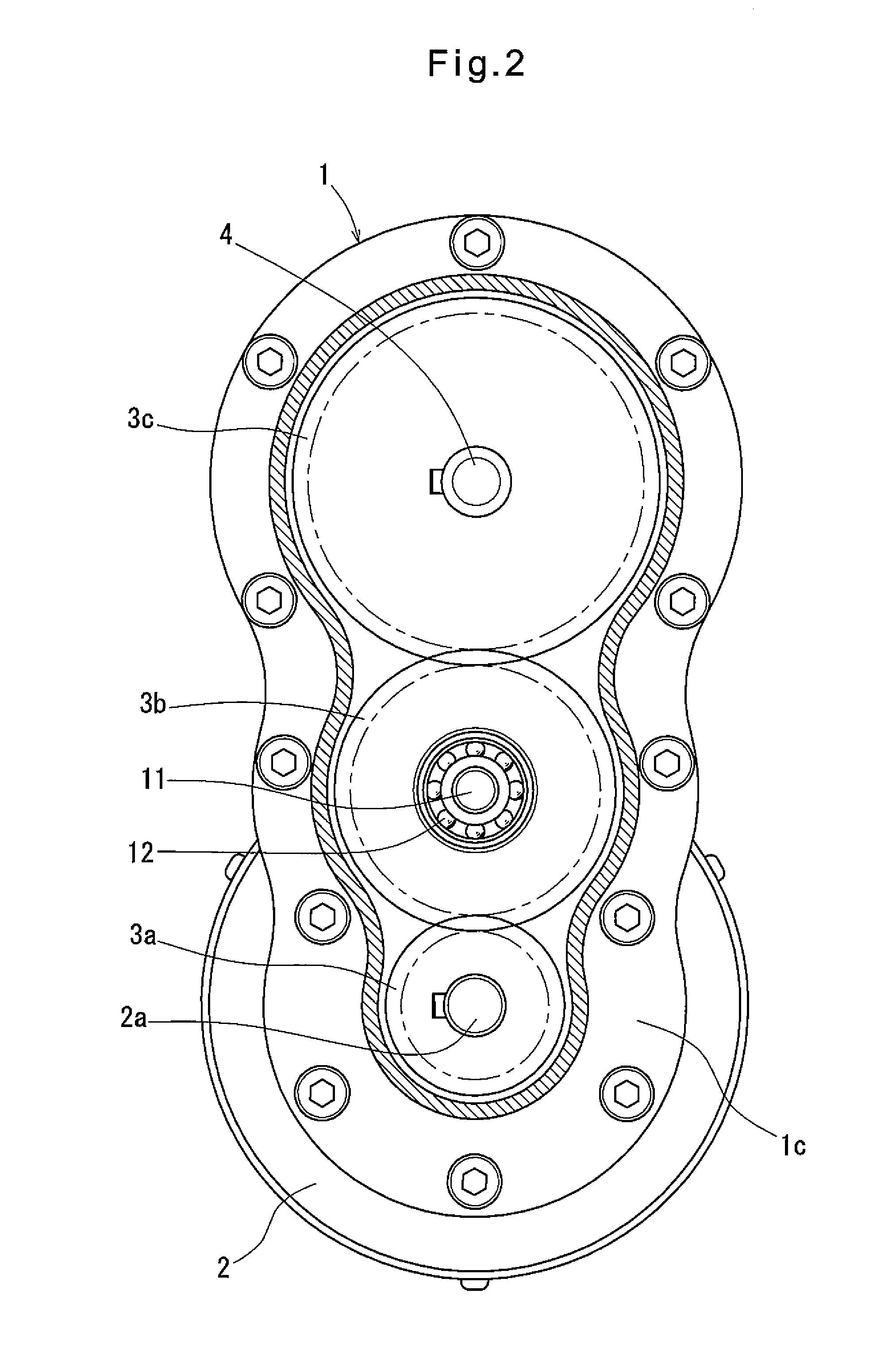
[0053]Embodiments of the present invention are now described with reference to the drawings. FIGS. 1 to 5 show an electric linear motion actuator embodying the present invention. As shown in FIGS. 1 to 3, the actuator includes a housing 1 having a cylindrical portion 1a, and a flange 1b protruding outwardly in one radial direction from one end of the cylindrical portion 1a. An electric motor 2 is mounted on the flange 1b to extend parallel to the cylindrical portion 1a.

[0054]The electric motor 2 has a rotor shaft 2a of which the rotation is transmitted to a rotary shaft 4 extending along the center axis of the cylindrical portion 1a through gears 3a, 3b and 3c. Four planetary rollers 7 are mounted between the rotary shaft 4 and an outer ring member 5 slidably fitted in the radially inner surface of the cylindrical portion 1a. The planetary rollers 7 are individually rotatably supported by a carrier 6.

[0055]A lid 1c is provided at the end of the housing 1 where there is the flange 1...


PUM


Abstract

A linear motion actuator is provided of which the output member can be smoothly moved linearly even when lateral moment acts on the output member. A carrier (6) supporting planetary rollers (7) is axially immovable, while an outer ring member (5), as the output member, is axially slidably fitted in the radially inner surface of a cylindrical portion (1a) of a housing (1), and is rotationally fixed to a driven member through keys (22). Hard plating layers are formed on the radially outer surface of a rotary shaft (4), the radially outer surfaces of the planetary rollers (7), including helical grooves (7a), and the surface of a helical rib member (5b) which is fixed to the radially inner surface of the outer ring member (5) forming a helical rib.

Description

TECHNICAL FIELD[0001]This invention relates to an electric linear motion actuator for converting the rotary motion of an electric motor to a linear motion and linearly driving a member to be driven, and an electric disk brake system using such an electric linear motion actuator.BACKGROUND ART[0002]Typically, a conventional electric linear motion actuator of this type includes a ball screw mechanism or a ball-ramp mechanism as a motion converter for converting rotary motion to linear motion.[0003]Ball screw mechanisms and ball-ramp mechanisms used in such electric linear motion actuators convert rotary motion to linear motion utilizing a thread having a lead angle, and inclined cam surfaces, respectively, such that they can increase power to a certain extent. But these mechanisms cannot increase power to an extent required in an electric disk brake system.[0004]Electric linear motion actuators including such a motion converter further include a speed reducer such as a planetary gear ...

Claims


Application Information

Patent Timeline
Patent Type & Authority Applications(United States)
IPC IPC(8): F16H25/20F16H25/24F16D65/18
CPCF16D65/18F16D2121/24F16D2125/40Y10T74/18656F16H25/2252H02K7/06F16D2125/48F16D2125/50F16H19/025
Inventor YAMASAKI, TATSUYAEGUCHI, MASAAKI
Owner NTN CORP
Why Eureka
Try Eureka