Motor control device

a technology of motor control and control device, which is applied in the direction of electric controllers, ignition automatic control, instruments, etc., can solve the problems heat generation or electric degradation of the motor, or the problem of mechanical degradation of the driven object, etc., and achieves simple computation and high functional characteristics.

Inactive Publication Date: 2012-12-06
MITSUBISHI ELECTRIC CORP
View PDF17 Cites 11 Cited by
  • Summary
  • Abstract
  • Description
  • Claims
  • Application Information

AI Technical Summary

Benefits of technology

[0023]The motor control device according to the present invention has a configuration of computing the motion correction value based on the predetermined reaction-force reference value and the deviation compensation driving force and a configuration of subtracting the motion correction value from the result of addition of the motion reference value and the motor motion detec...

Problems solved by technology

In the case of the parallel driving control described above, the following problem occurs due to accuracy of a position detector for each of the motors or mechanical accuracy when the drive...

Method used


Image

  • Motor control device
  • Motor control device
  • Motor control device

Examples


embodiment 1

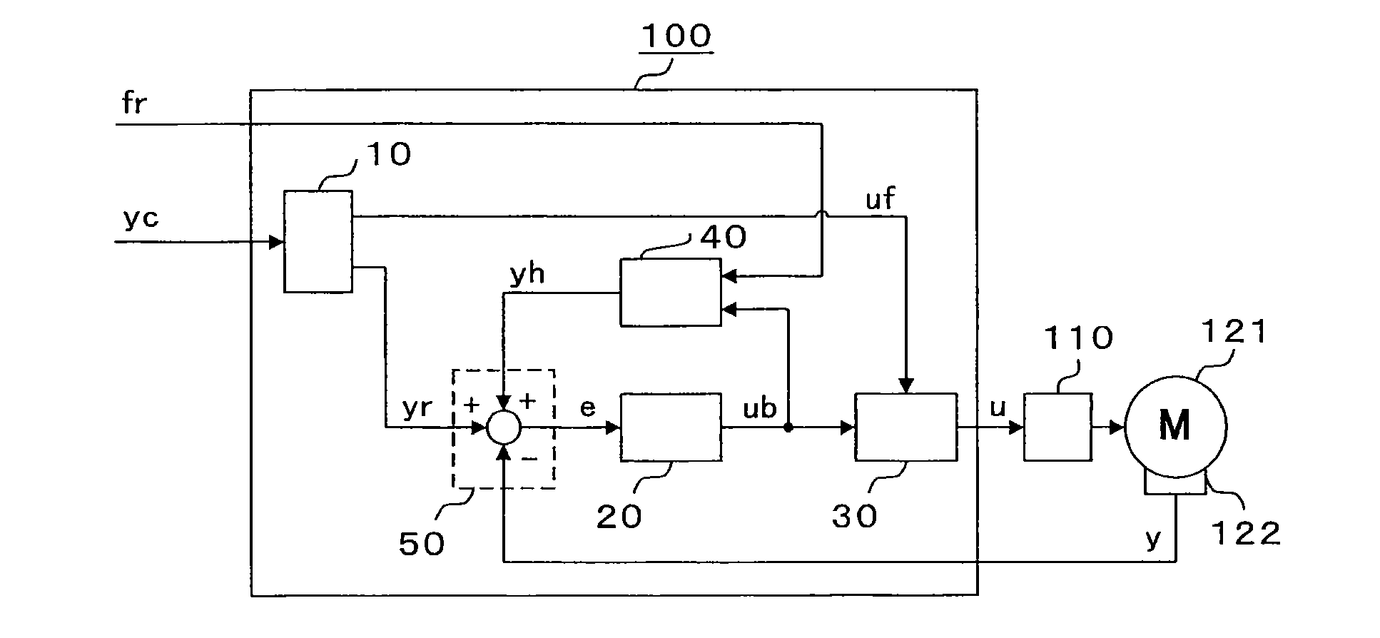
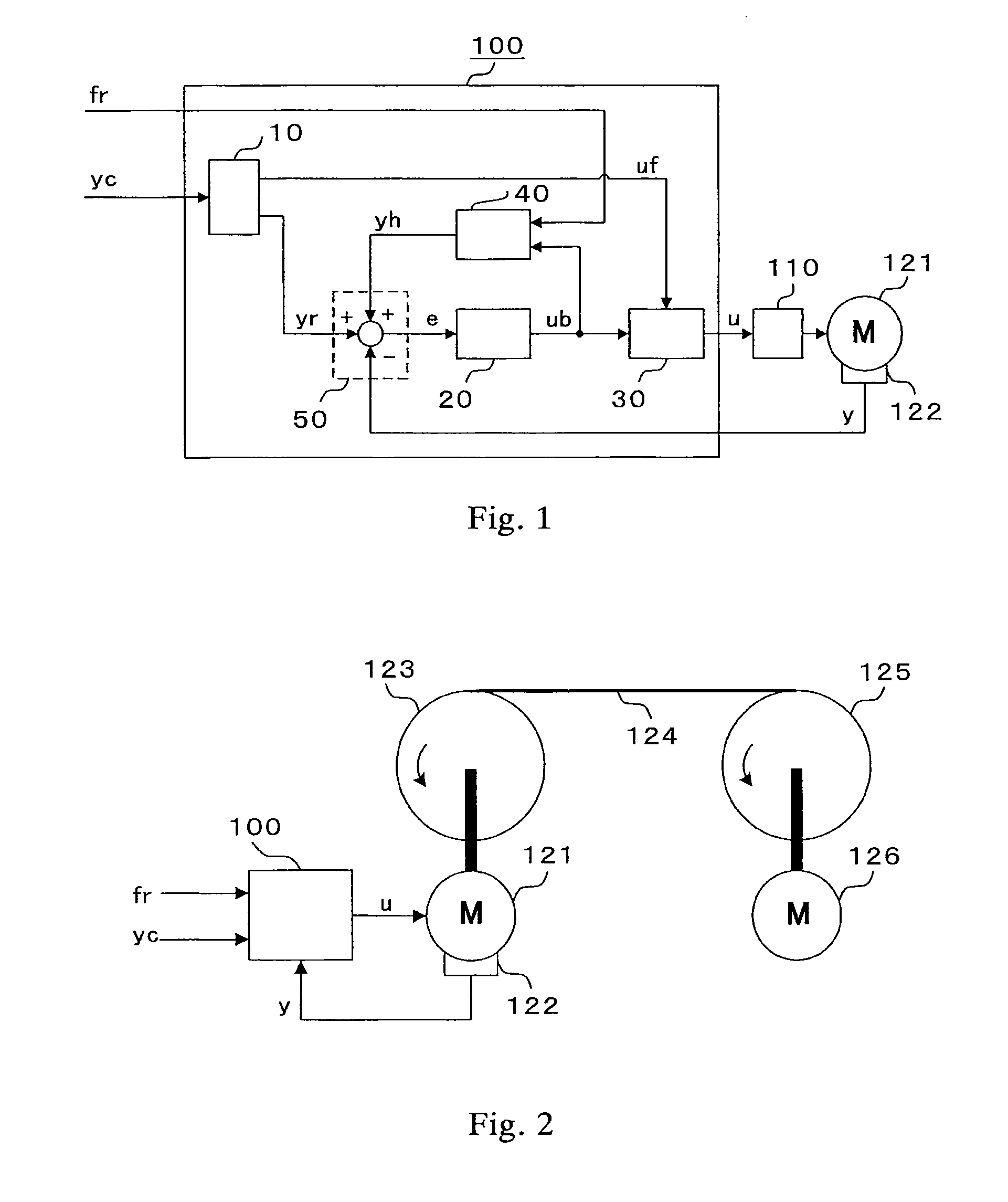
[0038]FIG. 1 is a block diagram illustrating a motor control device of Embodiment 1 of the present invention. First, an overall operation of a motor control device 100 is described. In Embodiment 1, a motor control device to be used for web handling control is described. A mode in which the web handling control is performed based on speed control is described. However, the control is not limited to the speed control and can be similarly realized even in the case where position control is performed.

[0039]The motor control device 100 illustrated in FIG. 1 includes a feedforward computing section 10, a deviation compensation computing section 20, a torque-command synthesizing section 30, a reaction-force compensation computing section 40, and a control-deviation computing section 50. Further, the motor control device 100 is connected to a motor 121 through an intermediation of a current controller 110. A motion detector 122 detects a motor speed (motor motion detection value) y corresp...

embodiment 2

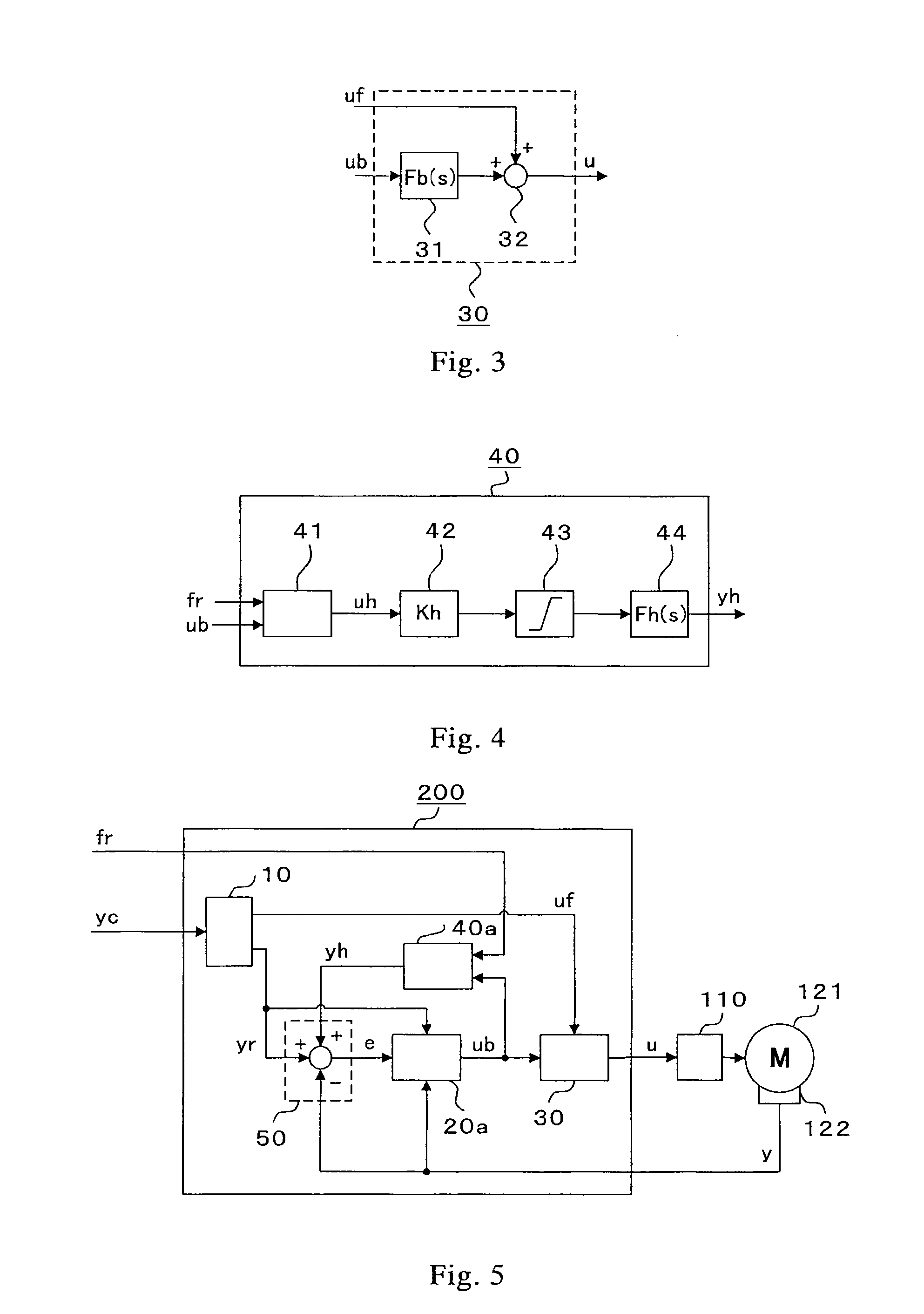
[0097]FIG. 5 is a block diagram illustrating a motor control device of Embodiment 2 of the present invention. A motor control device 200 illustrated in FIG. 5 includes the feedforward computing section 10, a deviation compensation computing section 20a, the torque-command synthesizing section 30, a reaction-force compensation computing section 40a, and the control-deviation computing section 50. The same reference numerals as those of FIG. 1 denote the same parts, and the description thereof is herein omitted.

[0098]The motor control device 200 of Embodiment 2 is to be used for the web handling control system illustrated in FIG. 2 as in the case of Embodiment 1 described above and replaces the motor control device 100 illustrated in FIG. 2. In comparison with the motor control device 100 of Embodiment 1 described above, the motor control device 200 of Embodiment 2 includes the deviation compensation computing section 20a and the reaction-force compensation computing section 40a havin...

embodiment 3

[0114]FIG. 8 is a block diagram illustrating a motor control device of Embodiment 3 of the present invention. Embodiment 3 supposes the use for parallel driving control in which a single driven object (work piece) is driven while being synchronously controlled by two motors. This embodiment deals with a problem in that an increased interaxial interference force due to a mechanical torsion between the motors is increased if the precise position control of each axis is simply performed for an error of the position detector for detecting the positions of the two motors or a mechanical error generated when the driven object and the motors are mechanically coupled to each other (hereinafter, referred to as an interaxial mechanical error) in the parallel driving control described above.

[0115]Although both the position control and the speed control are envisaged in the parallel driving control described above, parallel driving control with the position control is described in Embodiment 3....


PUM


Abstract

A motor control device includes: a feedforward computing section for computing a motion reference value and a feedforward driving force based on a motion command; a deviation compensation computing section for outputting a deviation compensation driving force by a control computation for reducing a control deviation; a driving-force command synthesizing section for outputting a driving-force command based on the feedforward driving force and the deviation compensation driving force; a reaction-force compensation computing section for computing a motion correction value based on a predetermined reaction-force reference value and the deviation compensation driving force; and a control-deviation computing section for computing the control deviation based on a deviation between the motion reference value and a motor motion detection value, and the motion correction value.

Description

TECHNICAL FIELD[0001]The present invention relates to a motor control device for driving various industrial mechanical devices.BACKGROUND ART[0002]As a first conventional art of a motor control device, for example, a usage called web handling control for continuously conveying a band-like material (web) by using a roll rotated by a motor as in the case of a steel rolling line is envisaged. In the conventional art for the usage described above, for the purpose of preventing imbalance of a load torque in motors connected by a conveyed material from being increased, a speed control unit has been provided with a function called drooping for a long time (for example, see Patent Literature 1).[0003]In the drooping control, a value corresponding to a proportional multiple of a signal indicative of a motor current, that is, a motor torque, is subtracted from a speed command, thereby providing a drooping characteristic (drooping) in which a motor speed decreases when the motor torque increas...

Claims


Application Information

Patent Timeline
IPC IPC(8): G05B11/42G05B11/06H02P29/00
CPCH02P29/022H02P5/52H02P29/032Y10S388/902Y10S388/91
Inventor IKEDA, HIDETOSHIMARUSHITA, YOSHIHIROUEDA, KOICHIROIGARASHI, YUJIMAEKAWA, KIYOSHI
Owner MITSUBISHI ELECTRIC CORP
Why Eureka
Try Eureka