Image-capturing optical lens assembly

a technology of optical lens and assembly, applied in the field of compact image-capturing optical lens assembly, can solve the problems of ineffective berration correction of optical system, and achieve the effect of favorable reducing the total track length of the lens assembly, good image quality, and favorable enlarged system field of view

Active Publication Date: 2012-12-06
LARGAN PRECISION
View PDF0 Cites 25 Cited by
  • Summary
  • Abstract
  • Description
  • Claims
  • Application Information

AI Technical Summary

Benefits of technology

[0008]With such an arrangement of optical elements, the optical system will have a field of view that is large enough; meanwhile, aberrations of the optical system can be favorably corrected to obtain good image quality.
[0009]In an image-capturing optical lens assembly of the present invention, the first lens element with negative refractive power allows the field of view of the system to be favorably enlarged. The second lens element and the third lens element with negative refractive power provide the main refractive power of the system, allowing the total track length of the lens assembly to be favorably reduced; also, the second lens element and the third lens element effectively distribute the refractive power of the system, thereby favorably reducing the sensitivity of the lens assembly. The fourth lens element with negative refractive power allows the aberration produced by the third lens element with positive refractive power to be corrected, and moreover, astigmatisms of the system can be effectively corrected. The fifth lens element having positive refractive power acts as a correction lens that can correct the high-order aberration, and cooperates with the fourth lens element having negative refractive power to achieve telephoto effects; such an arrangement can help to shorten the back focal length and further to reduce the total track length of the lens assembly.
[0010]In the image-capturing optical lens assembly of the present invention, the first lens element with negative refractive power has a convex object-side surface and a concave image-side surface. With this configuration, the field of view of the system can be favorably enlarged, and the refraction of incident light is more moderate for preventing the aberration from being excessively large; therefore, it is favorable for obtaining a better balance between a wide field of view and aberration correction. As to the second lens element, it is a meniscus lens element having a convex object-side surface and a concave image-side surface; this configuration can help correct the astigmatism produced by the first lens element when the image-side surface of the first lens element is a concave surface with a higher curvature radius. The third lens element is a bi-convex lens element having convex object-side and image-side surfaces; with this configuration, the refractive power of the third lens element can be favorably distributed, thereby further reducing the total track length of the lens assembly and sensitivity of the system. The fifth lens element has a convex image-side surface; this configuration allows the angle at which light is projected onto the sensor from the off-axis field to be effectively reduced, thereby increasing the photosensitivity of the system.
[0011]In the image-capturing optical lens assembly of the present invention, the aperture stop is disposed between the front lens group and the rear lens group. In a wide-angle optical system, it is particularly needed to correct distortions and chromatic aberrations of magnification, and this can be done by placing the aperture stop at a position where the refractive power of the system is balanced. Therefore, the aperture stop is disposed between the front lens group and the rear lens group in the present invention. By doing so, the front lens group comprising at least two lens elements allows the system to have a sufficient field of view; meanwhile, the rear lens group comprising at least three lens elements allows aberrations of the system to be effectively reduced, thereby achieving a wide field of view and good image quality at the same time. Also, such an arrangement of the aperture stop can help reduce the sensitivity of the system.

Problems solved by technology

While such arrangement facilitates the enlargement of the field of view, the aberration correction of the optical system is ineffective due to the inclusion of only one lens element in the rear lens group.

Method used


Image

  • Image-capturing optical lens assembly
  • Image-capturing optical lens assembly
  • Image-capturing optical lens assembly

Examples


embodiment 1

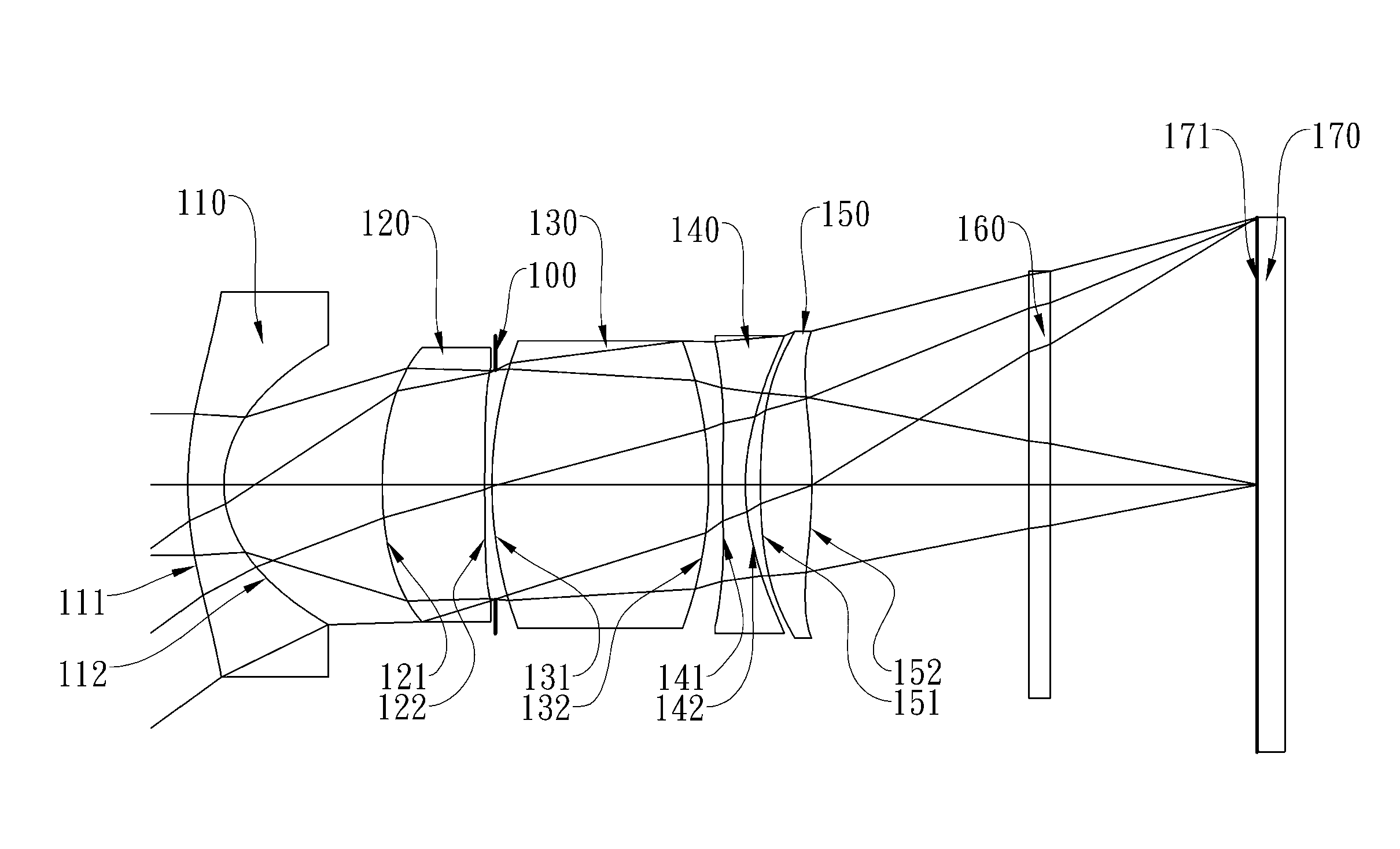
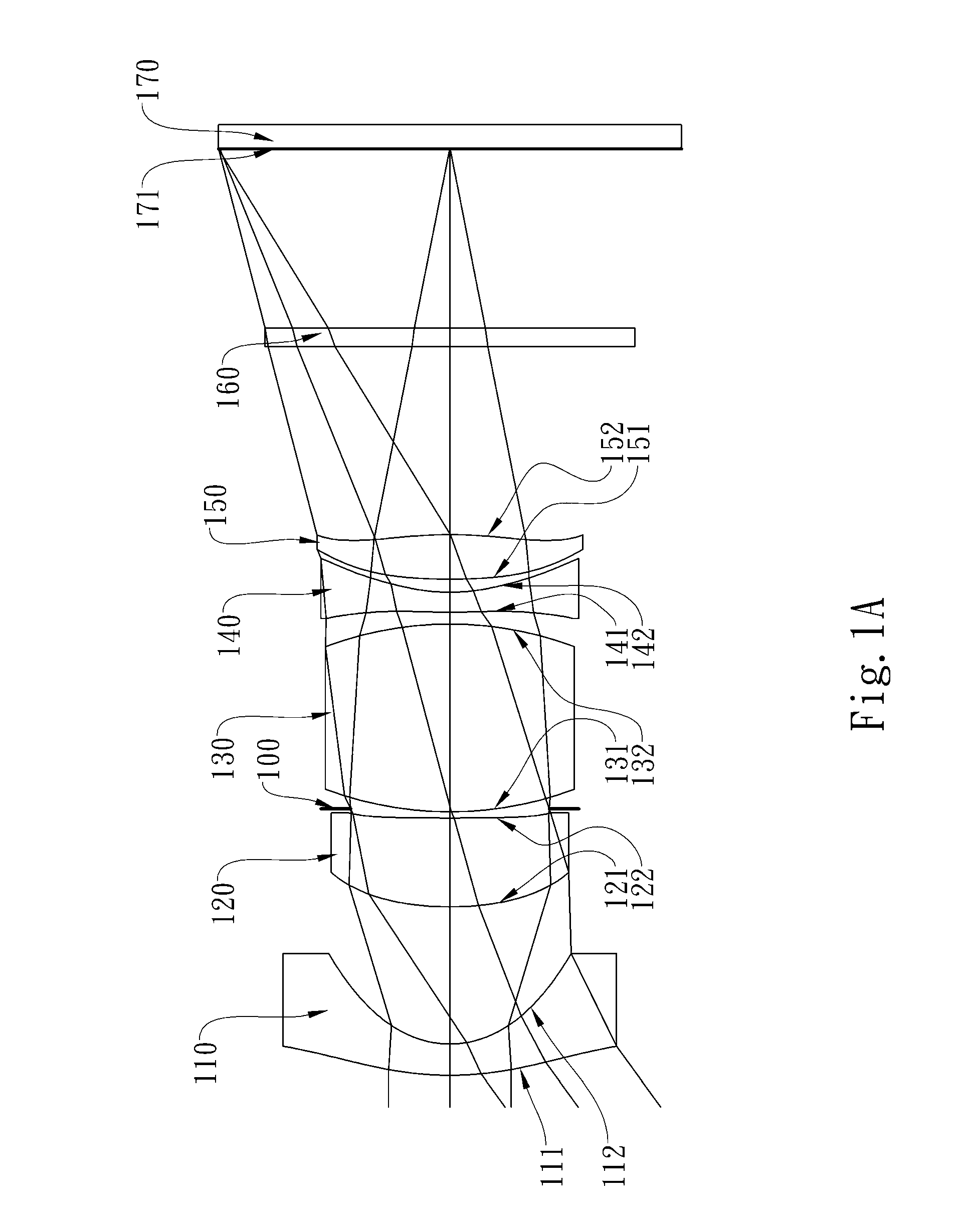
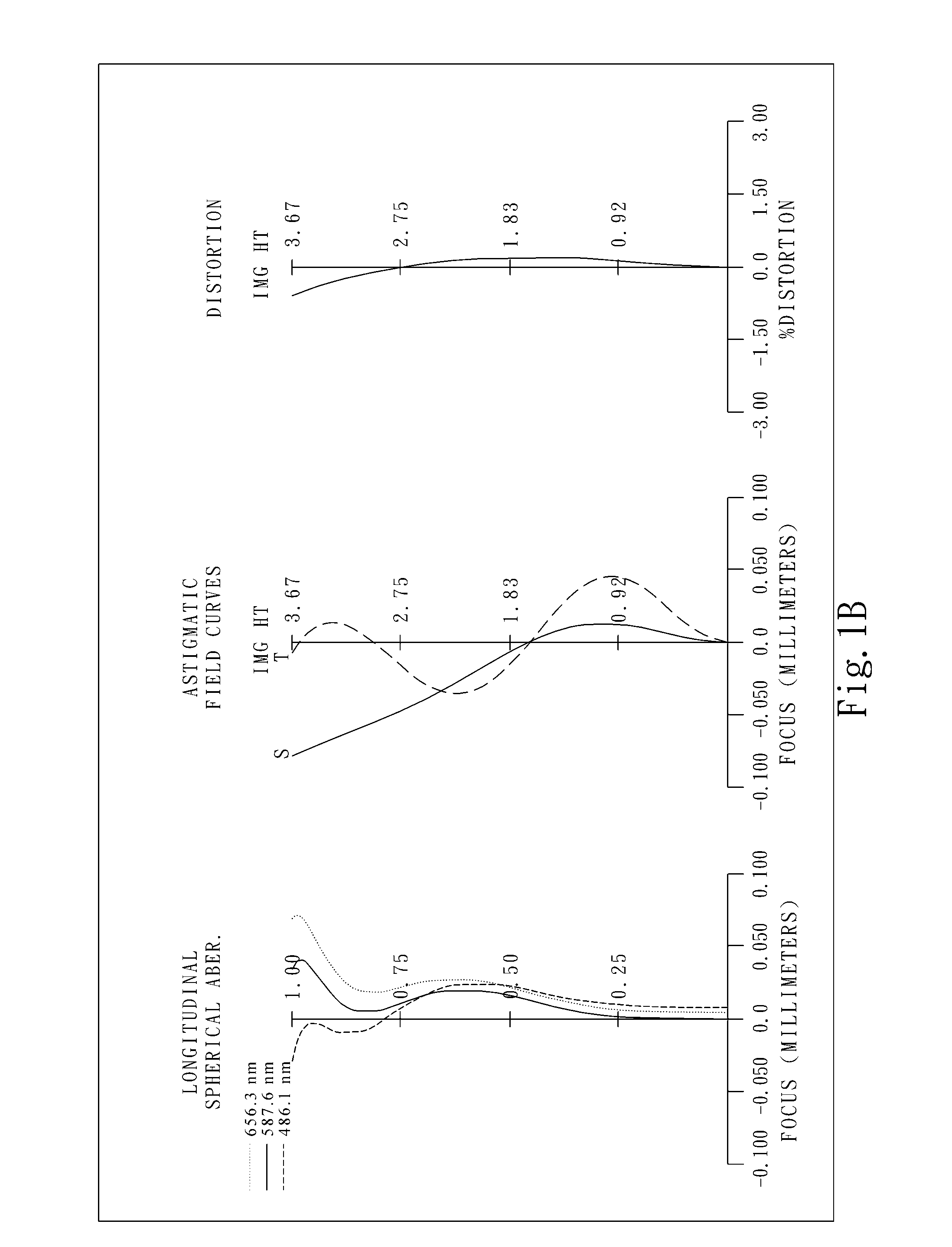
[0046]FIG. 1A shows an image-capturing optical lens assembly in accordance with the first embodiment of the present invention, and FIG. 1B shows the aberration curves of the first embodiment of the present invention. The image-capturing optical lens assembly in the first embodiment mainly comprises five lens elements, in order from an object side to an image side: a front lens group, an aperture stop 100 and a rear lens group, wherein:

[0047]the front lens group comprises, in order from the object side to the image side:

[0048]a plastic first lens element 110 with negative refractive power having a convex object-side surface 111 and a concave image-side surface 112, both of the surfaces 111 and 112 being aspheric; and

[0049]a plastic second lens element 120 with positive refractive power having a convex object-side surface 121 and a concave image-side surface 122, both of the surfaces 121 and 122 being aspheric;

[0050]the rear lens group comprises, in order from the object side to the i...

embodiment 2

[0077]FIG. 2A shows an image-capturing optical lens assembly in accordance with the second embodiment of the present invention, and FIG. 2B shows the aberration curves of the second embodiment of the present invention. The image-capturing optical lens assembly in the second embodiment mainly comprises five lens elements, in order from an object side to an image side: a front lens group, an aperture stop 200 and a rear lens group, wherein:

[0078]the front lens group comprises, in order from the object side to the image side:

[0079]a plastic first lens element 210 with negative refractive power having a convex object-side surface 211 and a concave image-side surface 212, both of the surfaces 211 and 212 being aspheric; and

[0080]a plastic second lens element 220 with positive refractive power having a convex object-side surface 221 and a concave image-side surface 222, both of the surfaces 221 and 222 being aspheric;

[0081]the rear lens group comprises, in order from the object side to th...

embodiment 3

[0088]FIG. 3A shows an image-capturing optical lens assembly in accordance with the third embodiment of the present invention, and FIG. 3B shows the aberration curves of the third embodiment of the present invention. The image-capturing optical lens assembly in the third embodiment mainly comprises five lens elements, in order from an object side to an image side: a front lens group, an aperture stop 300 and a rear lens group, wherein:

[0089]the front lens group comprises, in order from the object side to the image side:

[0090]a plastic first lens element 310 with negative refractive power having a convex object-side surface 311 and a concave image-side surface 312, both of the surfaces 311 and 312 being aspheric; and

[0091]a plastic second lens element 320 with positive refractive power having a convex object-side surface 321 and a concave image-side surface 322, both of the surfaces 321 and 322 being aspheric;

[0092]the rear lens group comprises, in order from the object side to the i...


PUM


Abstract

The present invention provides an image-capturing optical lens assembly comprising, in order from an object side to an image side, a front lens group, a stop, and a rear lens group. The front lens group comprises, in order from the object side to the image side: a first lens element with negative refractive power having a convex object-side surface and a concave image-side surface; and a second lens element with positive refractive power having a convex object-side surface and a concave image-side surface. The rear lens group comprises, in order from the object side to the image side: a third lens element with positive refractive power having a convex object-side surface and a convex image-side surface; a fourth lens element with negative refractive power; and a fifth lens element with positive refractive power having a convex image-side surface. With such an arrangement of optical elements, the optical system will have a field of view that is large enough; meanwhile, aberrations of the optical system can be favorably corrected to obtain good image quality.

Description

CROSS-REFERENCE TO RELATED APPLICATIONS[0001]This non-provisional application claims priority under 35 U.S.C. §119(a) on Patent Application No. 100119170 filed in Taiwan, R.O.C. on Jun. 1, 2011, the entire contents of which are hereby incorporated by reference.BACKGROUND OF THE INVENTION[0002]1. Field of the Invention[0003]The present invention relates to an image-capturing optical lens assembly, and more particularly, to a compact image-capturing optical lens assembly used in an electronic product.[0004]2. Description of the Prior Art[0005]In recent years, optical imaging lenses have been used in a wider range of products, and in particular, they are used in the following products for example: mobile phone cameras, webcams, vehicle cameras, security surveillance cameras and electronic game devices. The sensor of a general imaging lens is none other than CCD (Charge Coupled Device) or CMOS Sensor (Complementary Metal Oxide Semiconductor Sensor). Furthermore, as advances in semicondu...

Claims


Application Information

Patent Timeline
Patent Type & Authority Applications(United States)
IPC IPC(8): G02B9/60
CPCG02B13/0045G02B9/60
Inventor HSU, CHIH-WENCHOU, MING-TATSAI, TSUNG-HAN
Owner LARGAN PRECISION
Why Eureka
Try Eureka