
Electronic device with heat pipe chamber cover for dissipating heat

a technology of heat pipe and heat pipe, which is applied in the direction of cooling/ventilation/heating modification, semiconductor/solid-state device details, semiconductor devices, etc., can solve the problem of reducing the heat dissipation efficiency of the heat pip

Inactive Publication Date: 2012-12-06
FU ZHUN PRECISION IND SHENZHEN +1
View PDF8 Cites 25 Cited by
  • Summary
  • Abstract
  • Description
  • Claims
  • Application Information

AI Technical Summary

Benefits of technology

The present patent relates to an electronic device that uses a plate type heat pipe for improved heat dissipation. The device includes a cover, a base, side plates, a heat conduct plate, a wick structure, and a working medium. The cover acts as a shell of the heat pipe, reducing thermal resistance and improving heat dissipation efficiency. The side plates and heat conduct plate are integrally formed as a single monolithic piece of the same material, such as metal, and are soldered together. The device also includes a cavity for receiving the electronic element, with the side plates extending perpendicularly down from a periphery of the bottom surface of the cover. The wick structure is attached to the inner surface of the sealed chamber and acts as a flattened porous construction. The working medium is a liquid state in the evaporation section and a vapor state in the condensation section, carrying heat with it. The cover acts as a shell of the heat pipe, reducing thermal resistance and improving heat dissipation efficiency. The patent aims to provide an improved heat dissipation solution for electronic devices.

Problems solved by technology

However, thermal resistance between the heat pipe and the shell may be significant, and reduces the heat dissipation efficiency of the heat pipe.

Method used


Image

  • Electronic device with heat pipe chamber cover for dissipating heat
  • Electronic device with heat pipe chamber cover for dissipating heat
  • Electronic device with heat pipe chamber cover for dissipating heat

Examples


first embodiment

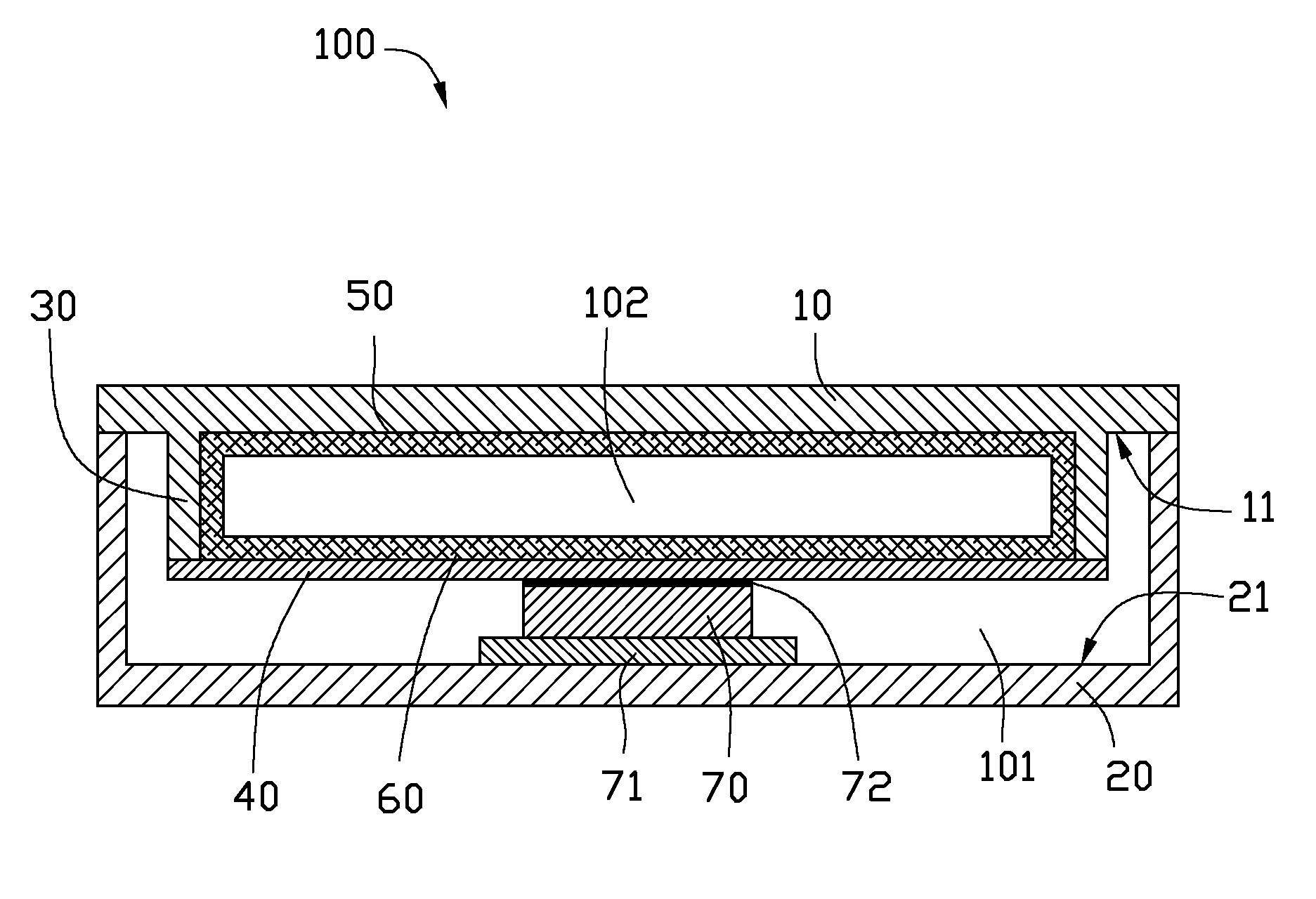
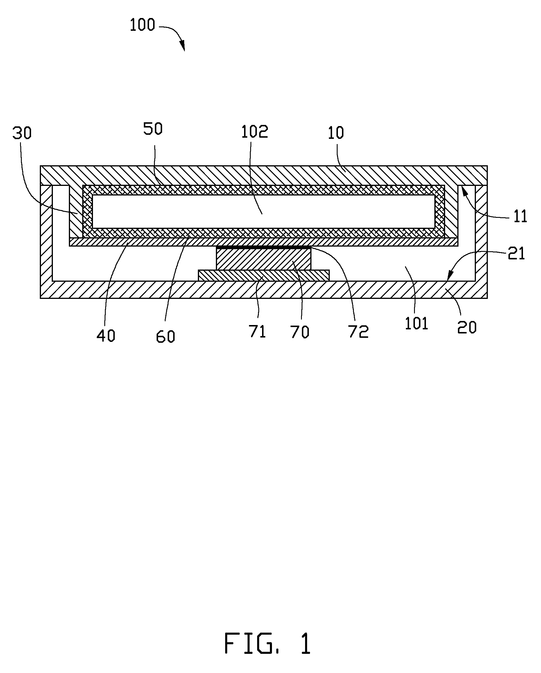
[0008]Referring to FIG. 1, an electronic device 100 according to the present disclosure is shown. The electronic device 100 can be a portable DVD (Digital Video Disc) player, a notebook computer, a mobile phone or a projector. The electronic device 100 includes a cover 10, a base 20 engaged with the cover 10, a plurality of side plates 30, a heat conduct plate 40, a wick structure 50, a working medium 60, and an electronic element 70.

[0009]The cover 10 is an elongated plate, and includes a planar bottom surface 11. The base 20 has an approximately U-shaped configuration. The cover 10 and the base 20 cooperatively define a cavity 101. The cavity 101 is used to receive the electronic element 70 and other electronic elements of the electronic device 100. The base 20 includes a top surface 21 opposite to the bottom surface 11 of the cover 10. The cover 10 and the base 20 are made of metal with good heat dissipation efficiency. The cover 10 and the base 20 can cooperatively form a shell ...

second embodiment

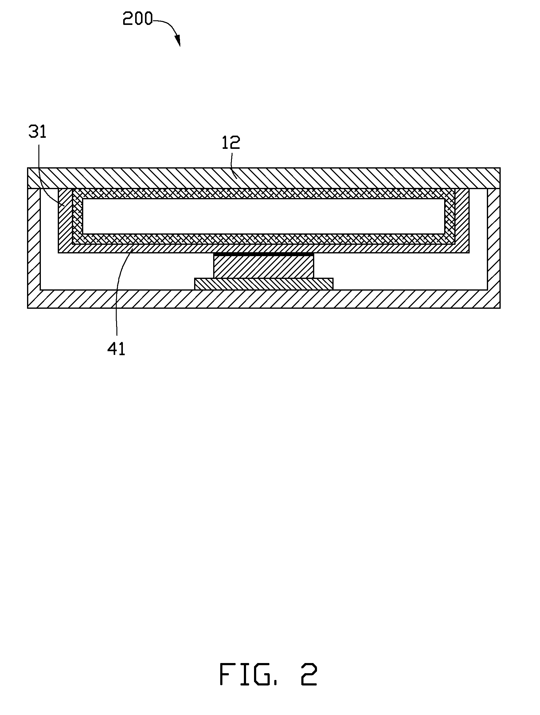
[0016]Referring to FIG. 2, an electronic device 200 according to the present disclosure is shown. Differing from the electronic device 100, the side plates 31 and the heat conduct plate 41 of the electronic device 200 are integrally formed as a single monolithic piece of the same material, namely metal. In other words, the side plates 31 and the heat conduct plate 41 are portions of a single body formed from the same metallic material. The side plates 31 are soldered to the cover 12.


PUM


Abstract

An exemplary electronic device includes a base, a cover, side plates, a heat conduct plate, a wick structure, a working medium and at least one electronic element. The cover and the base cooperatively define a cavity. The at least one side plate extends from the cover and receives in the cavity. The heat conduct plate and the at least side plate and the cover cooperatively defines a sealed chamber. The wick structure is attached to an inner surface of the sealed chamber. The working medium is received in the wick structure. The at least one electronic element is received in the cavity and thermally connected to the heat conduct plate.

Description

BACKGROUND[0001]1. Technical Field[0002]The present disclosure relates to electronic devices and, more particularly, to an electronic device using a plate type heat pipe.[0003]2. Description of Related Art[0004]Nowadays, numerous types of heat pipes are used to dissipate heat generated by electronic devices. A typical plate heat pipe is a hollow tube receiving working medium therein, and has a wick structure formed on an inner face thereof for drawing back the working medium. The heat pipe is maintained in thermal contact with a shell of an electronic device to dissipate heat generated from the electronic device. However, thermal resistance between the heat pipe and the shell may be significant, and reduces the heat dissipation efficiency of the heat pipe.[0005]Therefore, what is needed is an electronic device which can overcome the above described shortcomings.BRIEF DESCRIPTION OF THE DRAWINGS[0006]FIG. 1 is a cross-sectional view of an electronic device in accordance with a first ...

Claims


Application Information

Patent Timeline
Patent Type & Authority Applications(United States)
IPC IPC(8): H05K7/20
CPCH01L23/427H01L2924/0002H01L2924/00
Inventor YAN, QING-PINGWANG, DE-YUHU, JIANG-JUNHOU, CHUEN-SHU
Owner FU ZHUN PRECISION IND SHENZHEN
Learn More