Optical lens and optical lens plate

a technology of optical lenses and optical lenses, applied in the direction of instruments, semiconductor devices for light sources, lighting and heating apparatus, etc., can solve the problems of increasing the development and test time due to ratio adjustment, excessive mold design cost, and light pollution to the non-road side, so as to reduce the use of light, reduce the cost of manufacturing, and reduce the effect of light pollution

Inactive Publication Date: 2012-12-06
LEOTEK ELECTRONICS
View PDF4 Cites 72 Cited by
  • Summary
  • Abstract
  • Description
  • Claims
  • Application Information

AI Technical Summary

Benefits of technology

[0020]With the optical lens and the optical lens plate of the present invention, the second refraction angle on the second plane is changed through adjustment of a relative relation between the incident curved surface, the cone-shaped body and the design of the cone-shaped body. With the design of the lead angle surface, the utilization of the light is increased. Through adjustment of a relative relation between the light guide angle and the LED and a relative relation between the incident curved surface and the emitting curved surface, the first refraction angle on the first plane is changed. The optical lens plate of the present invention is applicable to a lamp, wherein an asymmetric light intensity distribution is achieved through the design of a single type of optical lens. Therefore, the luminous intensity distribution curve of the optical lens and the optical lens plate of the present invention has an asymmetric light distribution, so that the problems such as light pollution, low light utilization, and high manufacturing cost due to a complex design in the prior art can be solved when the optical lens and the optical lens plate of the present invention are applied to a street lamp.

Problems solved by technology

Therefore, problems of excessively high cost of mold design and increasing development and test time due to ratio adjustment exist.
However, the utilization of the LED street lamp with a symmetric light distribution on the road side (that is, a dotted line SS in FIG. 1E) to that on the non-road side (that is, a solid line HS in FIG. 1E) is about 50% to 50% (for example, one half of the light is projected to the road surface, and the other half of the light is projected to a building or a rice field), thereby causing light pollution to the non-road side (for example, the light projected to the building will interfere with the quality of human sleep or the light projected to the rice field will interfere with the growth of paddy rice.).
Therefore, problems that the design is complex and the assembly and production is not easy exist, thereby increasing the manufacturing cost of the street lamp.

Method used


Image

  • Optical lens and optical lens plate
  • Optical lens and optical lens plate
  • Optical lens and optical lens plate

Examples


Embodiment Construction

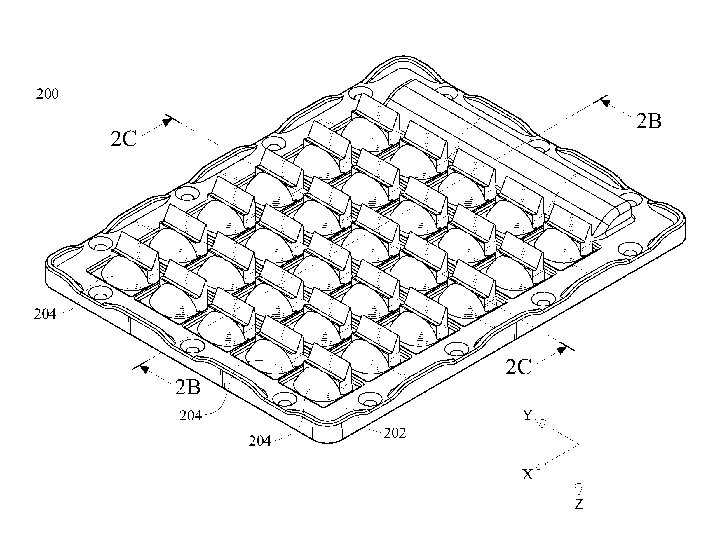
[0054]FIG. 2A is a schematic three-dimensional structural view of an embodiment of an optical lens plate of the present invention, and FIG. 2B is a schematic cross-sectional structural view along line 2B-2B of FIG. 2A. Referring to FIGS. 2A and 2B, in this embodiment, an optical lens plate 200 comprises a substrate 202 and thirty optical lenses 204, wherein the thirty optical lenses 204 are disposed on the substrate 202 in a 5×6 array (that is, a number of the optical lenses 204 disposed along a second axial direction Y is 5, and a number of the optical lenses 204 disposed along a first axial direction X is 6), but this embodiment is not intended to limit the present invention. That is, the number and the arrangement of the optical lenses 204 can be adjusted as required. Each optical lens 204 comprises an incident curved surface 206, a cone-shaped body 208, and an emitting curved surface 210. The emitting curved surface 210 may be, but not limited to, an elliptical curved surface (r...


PUM


Abstract

An optical lens includes a incident curved surface, a cone-shaped body, and a emitting curved surface. Light emitted from a light emitting diode (LED) has a first refraction angle on a first plane and a second refraction angle on a second plane after passing through the incident curved surface, the cone-shaped body, and the emitting curved surface. The first refraction angle is between 105 degrees and 145 degrees, and the second refraction angle is between 38 degrees and 65 degrees. The light is asymmetrically distributed on the second plane. Therefore, when the optical lens is applied to a street lamp, the light utilization on a road side may be increased.

Description

BACKGROUND OF THE INVENTION[0001]1. Field of Invention[0002]The present invention relates to an optical lens and an optical lens plate, and more particularly to an optical lens and an optical lens plate capable of achieving asymmetric distribution of light on a second plane.[0003]2. Related Art[0004]With the enhancement of people's awareness of environmental protection, various green electronic products have received attention according to the energy-saving and carbon-reduction effect. Due to characteristics of small volume, high brightness, long service life, and low power consumption, light emitting diode (LED) become an outstanding lighting appliance in the world wide. For example, the LED is used as a light source of traffic lights and flashlights in daily life. In addition to the application in traffic lights and flashlights, the LED can also be applied to street lamps.[0005]Light emitted from the LED should meet requirements of a specific light distribution for street lamp lig...

Claims


Application Information

Patent Timeline
Patent Type & Authority Applications(United States)
IPC IPC(8): F21V5/04
CPCG02B19/0066F21V5/007F21V5/04F21V5/08F21Y2101/02F21Y2105/001G02B19/0028F21W2131/103F21Y2105/10F21Y2115/10
Inventor SHIH, WEI-WEN
Owner LEOTEK ELECTRONICS
Why Eureka
Try Eureka