
Mobile communication system

a communication system and mobile technology, applied in the field of mobile communication system, can solve the problems of reducing the communication rate, rach involves a collision risk, interference between the macro cell or henb and the user equipment, etc., to prevent the decrease in the communication rate and interruption of communication, avoid interference, and avoid interference

Active Publication Date: 2012-12-06
MITSUBISHI ELECTRIC CORP
View PDF4 Cites 42 Cited by
  • Summary
  • Abstract
  • Description
  • Claims
  • Application Information

AI Technical Summary

Benefits of technology

[0065]According to the mobile communication system of the present invention, the mobile communication system includes a large-scale base station device having a large-scale coverage, a small-scale base station device having a small-scale coverage, and a user equipment device. The large-scale base station device notifies, via the user equipment device present in the large-scale coverage, the small-scale base station device present in the large-scale coverage of the interference-related information. This enables to easily notify the small-scale base station device of the interference-related information, which avoids interference in the mobile communication system and enables to prevent a decrease in communication rate and interruption of communication. Therefore, it is possible to avoid interference and achieve good communication quality even in a situation in which a large number of large-scale base station devices and small-scale base station devices are deployed in a complicated manner.

Problems solved by technology

The RACH involves a collision risk.
In the case where the HeNB is deployed in the coverage of a macro cell, interference occurs between the macro cell or HeNB and a user equipment (UE).
Such interference hinders the communication between the user equipment (UE) and the macro cell or HeNB, which decreases the communication rate.
If the interference power becomes larger, communication cannot be made.

Method used


Image

  • Mobile communication system
  • Mobile communication system
  • Mobile communication system

Examples


first embodiment

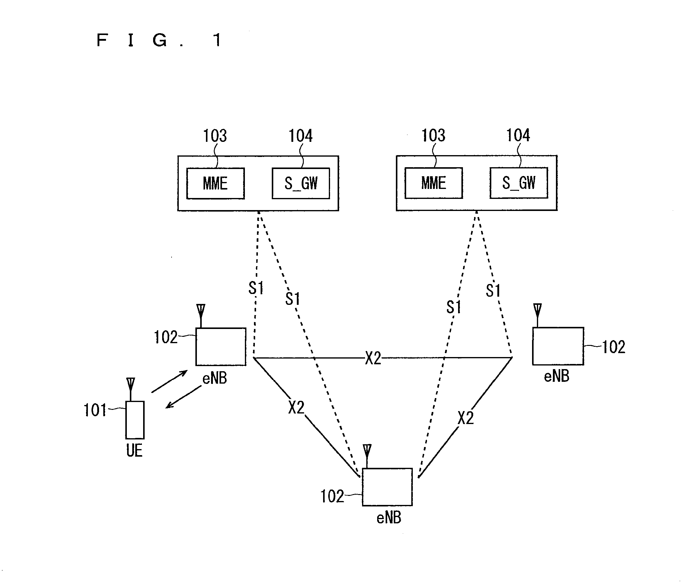
[0095]FIG. 7 is a block diagram showing an overall configuration of an LTE mobile communication system, which is currently under discussion of 3GPP. Currently, 3GPP is studying an overall system configuration including closed subscriber group (CSG) cells (Home-eNodeBs (Home-eNB; HeNB) of E-UTRAN, Home-NB (HNB) of UTRAN) and non-CSG cells (eNodeB (eNB) of E-UTRAN, NodeB (NB) of UTRAN, and BSS of GERAN) and, as to E-UTRAN, is proposing the configuration as shown in FIG. 7 (see Chapter 4.6.1 of Non-Patent Document 1).

[0096]FIG. 7 is described. A user equipment device (hereinafter, referred to as “user equipment” or “UE”) 71 is capable of performing radio communication with a base station device (hereinafter, referred to as “base station”) 72 and transmits / receives signals through radio communication. The base stations 72 are classified into an eNB 72-1 that is a macro cell and a Home-eNB 72-2 that is a local node. The eNB 72-1 corresponds to a large-scale base station device and has a ...

fourth modification

of First Embodiment

[0228]While the HeNBs to be notified of the HII are HeNBs present in a certain received power range from a macro cell in the first embodiment, in the present modification, the HeNBs to be notified of the HII are HeNBs present in the range with a specific distance or a path loss from the macro cell.

[0229]The method of judging HeNBs deployed in the range of a specific path loss from a macro cell is achieved by using the path loss in place of the received power disclosed in the first embodiment to the third modification of the first embodiment. For example, in the case of application to the first embodiment, in Step ST1401 of FIG. 14, the HeNB is only required to derive a path loss. The path loss may be derived using the received power measurement results of a cell nearby and the transmission power value of the cell that has been broadcast from the neighbor cell. In Step ST1404, Step ST1405 and Step ST1406 of FIG. 14, a path loss may be used in place of the received ...

fifth modification

of First Embodiment

[0234]While the HeNBs notified of the HII are HeNBs present in a specific received power range from a macro cell in the first embodiment, in the present modification, HeNBs notified of the HII are HeNBs present in a specific direction range with respect to a macro cell.

[0235]The method of judging HeNBs deployed in a specific direction range with respect to a macro cell is achieved with the use of the location information disclosed in the fourth modification of the first embodiment. From the location information of the HeNB and the location information of the macro cell, it is possible to derive a direction in which the HeNB is deployed with respect to the macro cell. Therefore, it suffices that whether or not a HeNB is in a specific direction range is judged based on the information on the direction with respect to the macro cell, which has been derived from the location information.

[0236]Further, from the location information of a UE and the location information ...


PUM


Abstract

A mobile communication system capable of easily notifying the interference-related information and avoiding interference in a situation in which a macro cell and local nodes are deployed to coexist. In the system, a macro cell (eNB) notifies, via user equipments (UEs) present in a coverage, HeNBs present in the coverage of the interference-related information related to the interference to a physical resource to be used, for example, a high interference indication (HII) and an overload indicator (OI).

Description

TECHNICAL FIELD[0001]The present invention relates to a mobile communication system in which a base station performs radio communication with a plurality of user equipments.BACKGROUND ART[0002]Commercial service of a wideband code division multiple access (W-CDMA) system among so-called third-generation communication systems has been offered in Japan since 2001. In addition, high speed down link packet access (HSDPA) service for achieving higher-speed data transmission using a downlink has been offered by adding a channel for packet transmission (high speed-downlink shared channel (HS-DSCH)) to the downlink (dedicated data channel, dedicated control channel). Further, in order to increase the speed of data transmission in an uplink direction, service of a high speed up link packet access (HSUPA) system has been offered. W-CDMA is a communication system defined by the 3rd generation partnership project (3GPP) that is the standard organization regarding the mobile communication system...

Claims


Application Information

Patent Timeline
Patent Type & Authority Applications(United States)
IPC IPC(8): H04W72/08H04W72/04H04W72/54
CPCH04W84/045H04W92/20H04W28/06H04L1/1812H04L1/0002H04L1/0026H04W72/12H04W72/20H04W72/541H04W28/0236
Inventor MOCHIZUKI, MITSURUMAEDA, MIHOIWANE, YASUSHIKAKEHI, YUJINAKAZAWA, MASAYUKISUEMITSU, TAISEI
Owner MITSUBISHI ELECTRIC CORP
Learn More