Image forming apparatus

a technology of image forming apparatus and forming apparatus, which is applied in the direction of electrographic process apparatus, instruments, optics, etc., can solve the problems of image failure, image forming apparatus malfunction, damage to the substrate of the power source, and dramatic increase in cos

Inactive Publication Date: 2012-12-06
RICOH KK
View PDF3 Cites 54 Cited by
  • Summary
  • Abstract
  • Description
  • Claims
  • Application Information

AI Technical Summary

Problems solved by technology

More particularly, when the toner is transferred on the recording medium having large asperity, the toner cannot be transferred on the concave portion sufficiently, which may generate image failure in which toner image is partly absent.
However, when the transfer mode is switched in this example, a cur...

Method used


Image

  • Image forming apparatus
  • Image forming apparatus
  • Image forming apparatus

Examples


second embodiment

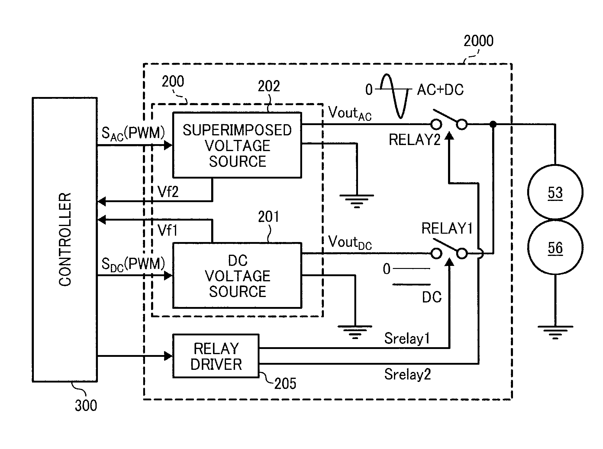
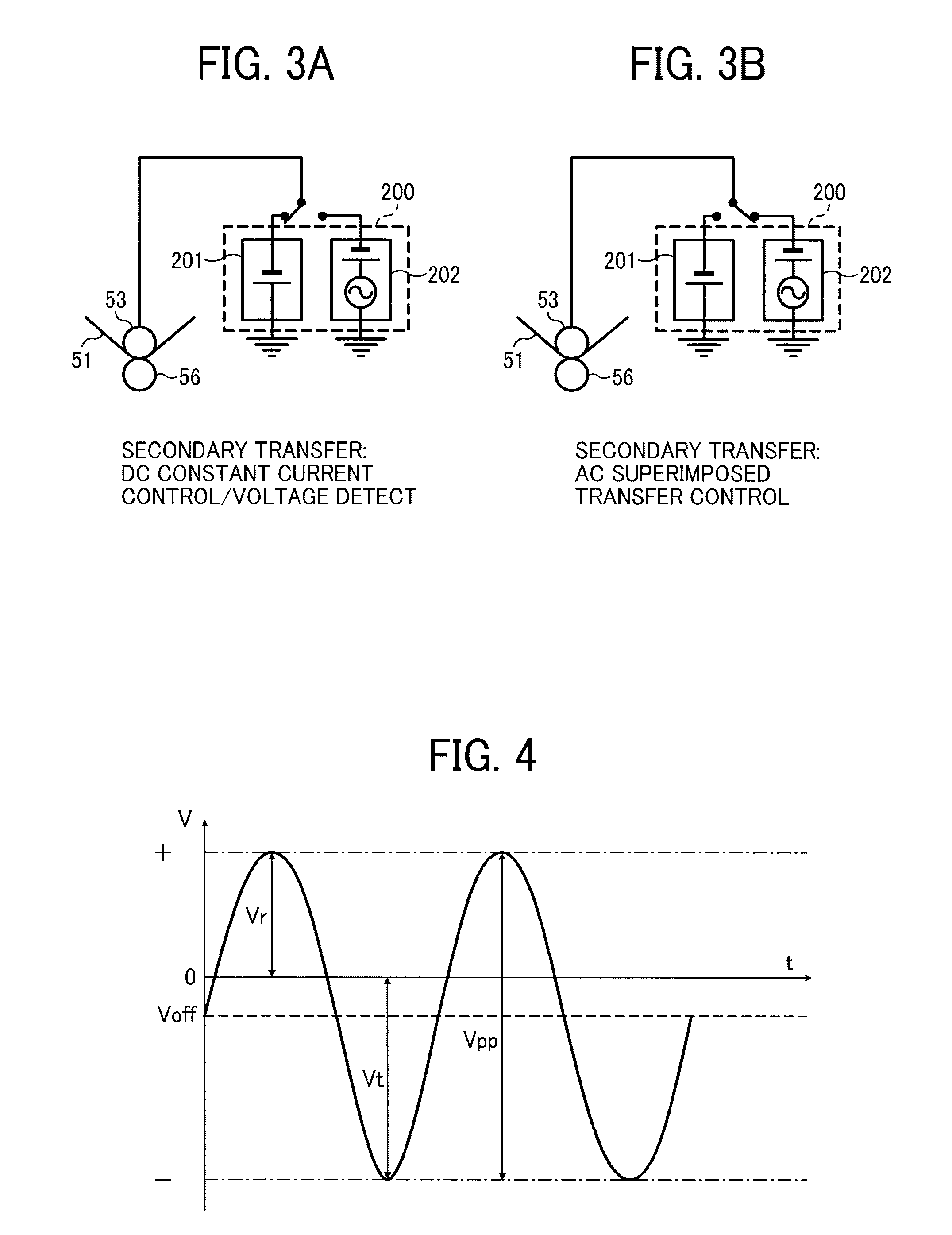
[0114]Although the transfer member is not limited to make a nip, a non-contact transfer method using charger can be adopted. FIG. 12 is a schematic diagram illustrating a secondary transfer member according to a second embodiment. As illustrated in FIG. 12, in the second embodiment, a transfer charger 156 as a non-contact type transfer member faces the secondary transfer rear roller 53 is disposed outside loop of the intermediate transfer belt 51. The secondary transfer bias power supply 200 applies the DC bias and the superimposed bias to the transfer charger 156 while switching between the DC bias and the superimposed bias. As for the secondary transfer bias power source, the secondary transfer bias power supply 200 according to the first embodiment can be adopted.

[0115]It is to be noted that, in the second embodiment, the polarity of the DC component of the transfer bias applied to the transfer charger 156 is opposite to the polarity of the toner charging polarity. The transfer b...


PUM


Abstract

An image forming apparatus, includes an image bearer to bear a toner image; a transfer member to transfer the toner image; a transfer bias applicator to apply a transfer bias to the transfer member, the transfer bias applicator including a direct current voltage source to apply a direct current transfer bias constituted by a direct current voltage to the transfer member; and a superimposed voltage source to apply a superimposed transfer bias in which an alternating current voltage is superimposed on a direct current voltage to the transfer member; and a controller to switch between a direct current transfer mode during which the direct current transfer bias is applied to transfer the toner image and a superimposed transfer mode during which the superimposed transfer bias is applied to transfer the toner image while the direct current voltage source and the superimposed voltage source are off.

Description

CROSS-REFERENCE TO RELATED APPLICATIONS[0001]This patent application is based on and claims priority pursuant to 35 U.S.C. §119 to Japanese Patent Application Nos. 2011-124141, filed on Jun. 2, 2011 and 2011-179488, filed on Aug. 19, 2011 in the Japan Patent Office, the entire disclosures of which are hereby incorporated by reference herein.FIELD OF THE INVENTION[0002]1. Technical Field[0003]The present disclosure relate to an image forming apparatus, such as a copier, a facsimile machine, a printer, or a multi-functional system including a combination thereof.[0004]2. Description of the Related Art[0005]In electrophotographic image forming apparatuses, an electrostatic latent image, which is obtained by forming optical image data on an image carrier (e.g., a photoreceptor) that is uniformly charged in advance, is rendered visible with toner from a development device. An image is formed on a recording medium by transferring the visible image directly or indirectly onto the recording...

Claims


Application Information

Patent Timeline
IPC IPC(8): G03G15/16
CPCG03G2215/0129G03G15/1645
Inventor SHIMIZU, YASUNOBUHAGA, HIROYOSHITAKEUCHI, TOMOKAZUOGIYAMA, HIROMISENGOKU, KENJIFUJITA, JUNPEI
Owner RICOH KK
Why Eureka
Try Eureka