Fan control circuit

Inactive Publication Date: 2012-12-06
HONG FU JIN PRECISION IND (SHENZHEN) CO LTD +1
View PDF10 Cites 4 Cited by
  • Summary
  • Abstract
  • Description
  • Claims
  • Application Information

AI Technical Summary

Benefits of technology

[0012]As the computer starts up, the control pin 12 of the GPIO interface 95 outputs a high-level voltage control signal to the input of the NOT gate 50. The NOT gate 50 inverts the signal which is then output to the enable pin OE and the signal input A of the electronic switch chip 40. The electronic switch chip 40 is turned on, and the low-level signal from the signal input A of the electronic switch 40 is transmitted to the rotational speed control pin 16 of the fan controller 90 via the signal output Y of the electronic switch chip 40. The governing signal at the rotational speed control pin 16 and the control pin 14 of the fan interface 30 is thereby low, which leaves the fan 20 turned off.

Problems solved by technology

The power consumed by the interior components of the server, such as motherboards, hard disk drives and fans, can be up to a thousand kilowatts at the start up moment, which may cause instability in the power supply to the server, and high power consumption.
Delay circuitry has been used to make the fans start operating after a preset delay period, however, many delay circuits include multiple extra components, which results in high cost.

Method used


Image

  • Fan control circuit
  • Fan control circuit

Examples


Embodiment Construction

[0008]The disclosure, including the accompanying drawing, is illustrated by way of example and not by way of limitation. It should be noted that references to “an” or “one” embodiment in this disclosure are not necessarily to the same embodiment, and such references mean at least one.

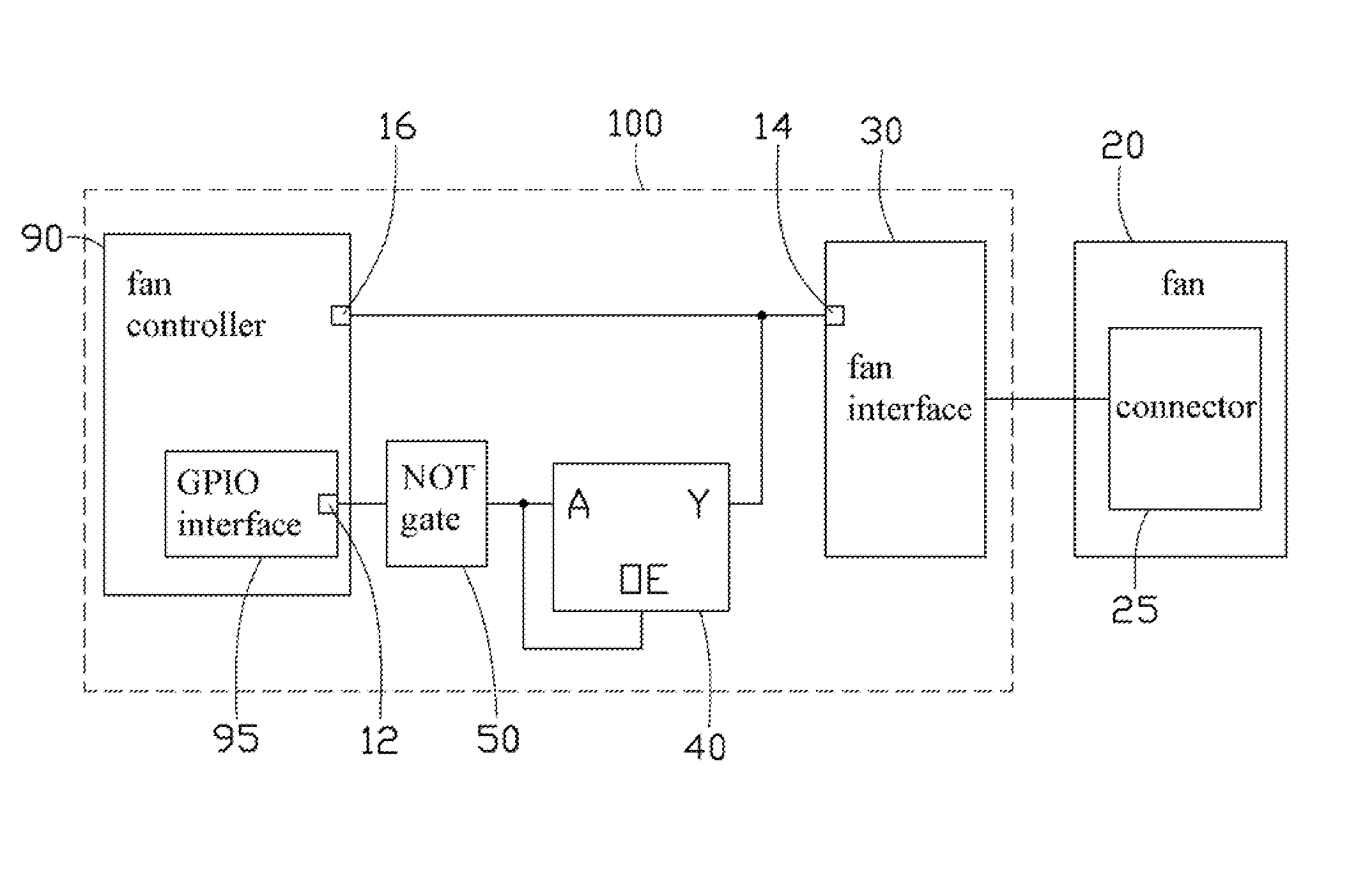
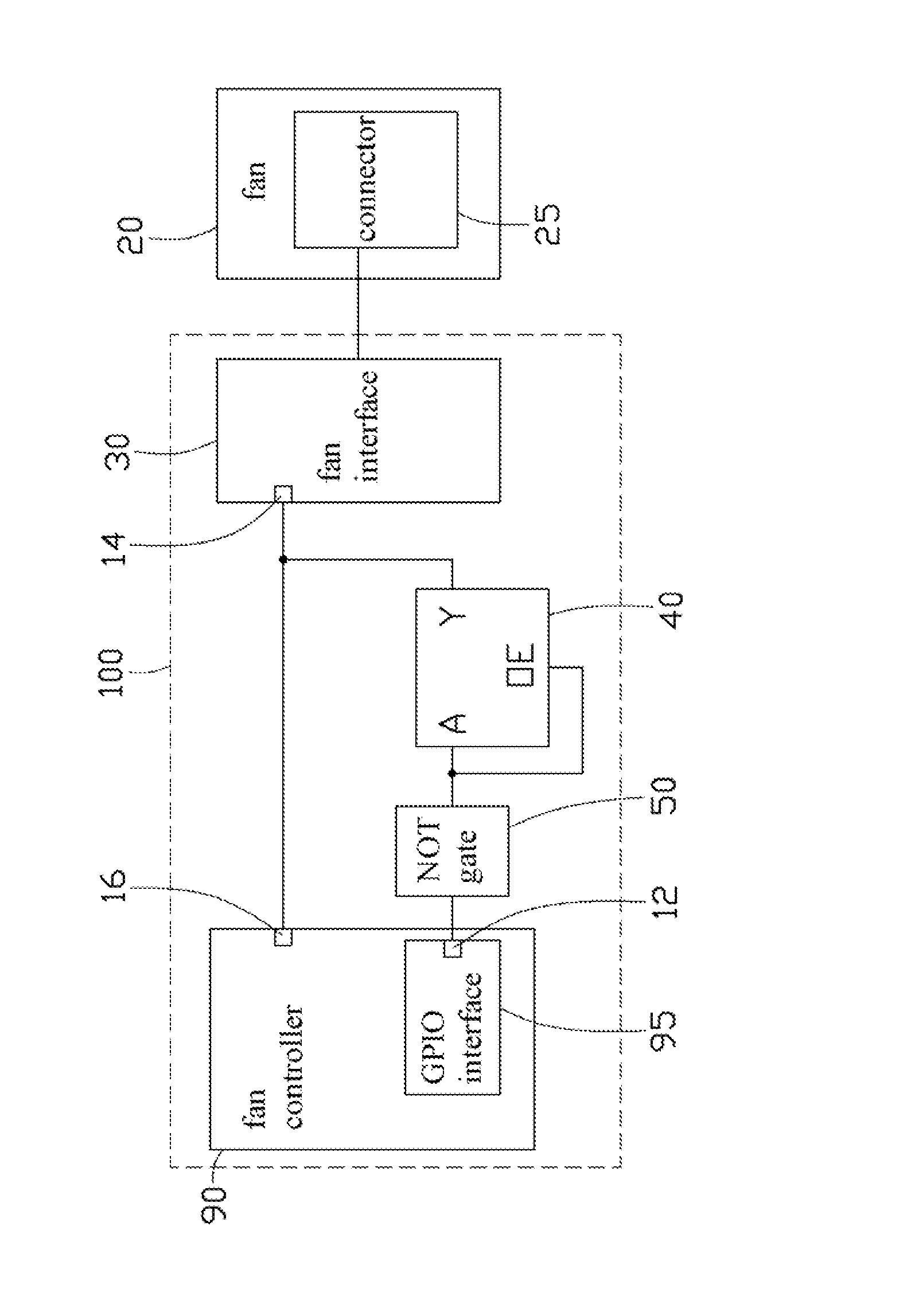
[0009]Referring to the FIGURE, an exemplary embodiment of a fan control circuit 100 of a computer includes a fan controller 90, an electronic switch chip 40, a NOT gate 50, and a fan interface 30 for connecting with a connector 25 of a fan 20.

[0010]The fan controller 90 includes a rotational speed control pin 16 which outputs a pulse width modulation (PWM) signal, and a general purpose input / output (GPIO) interface 95 with a control pin 12 for outputting a voltage control signal. The rotational speed control pin 16 is connected to a control pin 14 of the fan interface 30 to transmit the PWM signal to the fan interface 30 to control the operation of the fan 20. The control pin 12 of the GPIO interface 95...


PUM


Abstract

A fan control circuit of a computer includes a fan interface connected to a connector of a fan, a fan controller, a NOT gate, and an electronic switch. The fan controller outputs a PWM signal to the fan interface to control the operation of the fan, and includes a GPIO interface to output a voltage control signal to the NOT gate to switch the electronic switch on or off. A signal output of the electronic switch is connected to the fan interface. The voltage control signal is high level at the start up moment of the computer, and thus does not turn on the fan via the electronic switch. After a preset delay period, the voltage control signal is turned low by the fan controller so that the fan interface receives the PWM signal.

Description

CROSS-REFERENCE TO RELATED APPLICATIONS[0001]This application is related to a U.S. patent application entitled “FAN CONTROL CIRCUIT,” with the same assignee as the instant application and with the Attorney Docket No. US40027. The disclosure of the above identified application is incorporated herein by reference.BACKGROUND[0002]1. Technical Field[0003]The present disclosure relates to a fan control circuit.[0004]2. Description of Related Art[0005]A server typically includes multiple fans, which rotate at full speed at the moment of the server being started up. The power consumed by the interior components of the server, such as motherboards, hard disk drives and fans, can be up to a thousand kilowatts at the start up moment, which may cause instability in the power supply to the server, and high power consumption. Delay circuitry has been used to make the fans start operating after a preset delay period, however, many delay circuits include multiple extra components, which results in...

Claims


Application Information

Patent Timeline
IPC IPC(8): F04B49/00
CPCF04D27/004Y02B30/70
Inventor WU, KANGCHEN, GUO-YI
Owner HONG FU JIN PRECISION IND (SHENZHEN) CO LTD
Why Eureka
Try Eureka