
Dental handpiece

a handpiece and hand-held technology, applied in the field of dental handpieces, can solve the problems of rotating instability and damage to the gear, and achieve the effect of improving the dust control function in the head section and being difficult to have troubles

Active Publication Date: 2012-12-06
NAKANISHI INC
View PDF11 Cites 1 Cited by
  • Summary
  • Abstract
  • Description
  • Claims
  • Application Information

AI Technical Summary

Benefits of technology

[0008]It is an object of the present invention to provide a dental handpiece which has improved dust control function in the head section, and is hard to have troubles.

Problems solved by technology

This may cause entry of dust further into the head housing to damage the gear and lead to rotation instability.

Method used


Image

  • Dental handpiece
  • Dental handpiece
  • Dental handpiece

Examples


Embodiment Construction

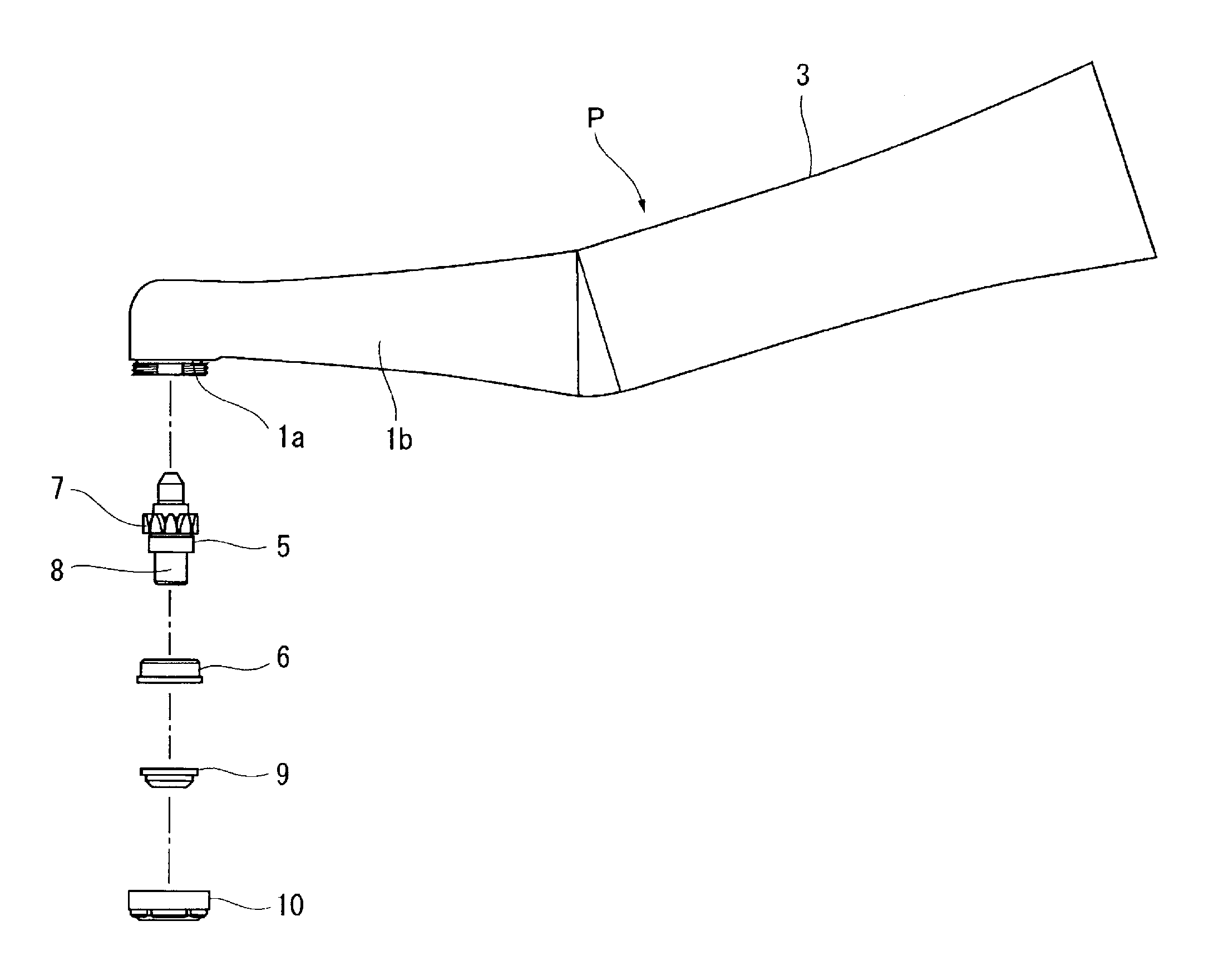
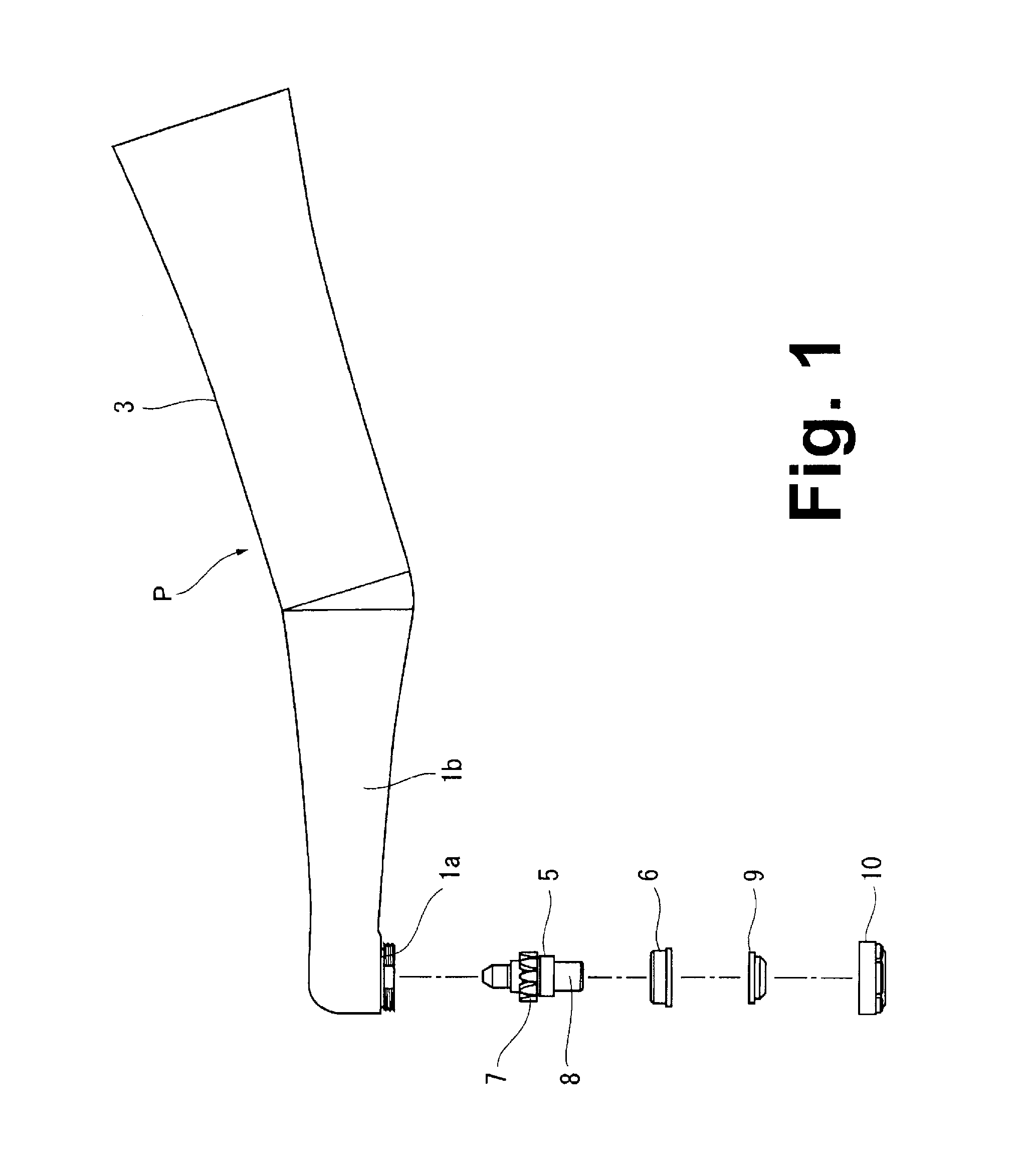
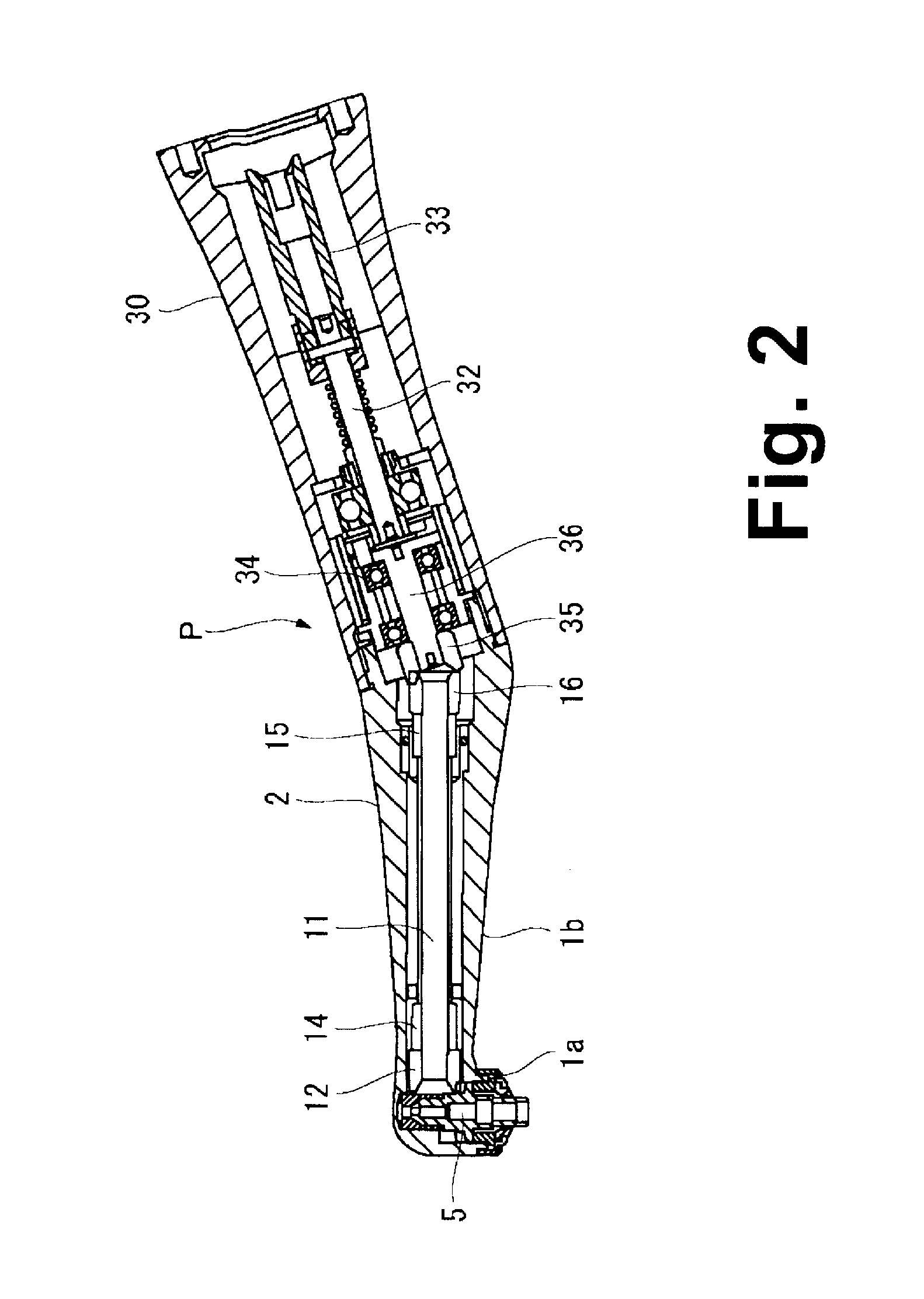
[0025]The present invention will now be explained in detail with reference to the attached drawings, wherein FIG. 1 shows the overall structure of the dental handpiece according to the present invention, and FIGS. 2 to 4 show the internal structure or various part structures of the handpiece.

[0026]Referring to FIG. 1, a dental handpiece P has a head 1a for drivingly holding a treatment tool therein, and a neck 1b extending proximally from the head 1a and generally cylindrically, which two are formed integrally as a head-neck section 2. The handpiece P further has a generally cylindrical grip section 3 detachablly connected to the proximal end of the head-neck section 2, and a drive unit (not shown) detachably connected to the proximal end of the grip section 3.

[0027]Referring to FIG. 4, the head la has a generally cylindrical head housing 4, a gear shaft 5 accommodated in the head housing 4, and a retaining member 6 for rotatably retaining the gear shaft 5 in the head housing 4. The...


PUM


Abstract

A dental handpiece is disclosed which has a head housing, a gear shaft having a gear part with gear teeth and a shaft part extending from the gear part, and a dust control seal sealingly fit on the circumferential surface of the shaft part of the gear shaft. The dust control seal is an annular member, and has a seal body, a first lip projecting radially inwardly from the seal body, and a second lip projecting radially inwardly from the seal body above and spaced apart from the first lip, with a space defined between a contact area between the first lip and the shaft part, and a contact area between the second lip and the shaft part.

Description

FIELD OF ART[0001]The present invention relates to a dental handpiece, in particular, a dental handpiece having an improved gear shaft assembled in the head section to hold a dental treatment tool, and an improved dust control seal attached to the gear shaft.BACKGROUND ART[0002]There are known a dental handpiece having a head section accommodating a bur sleeve in which a dental treatment tool is held, a neck section containing a power transmission shaft, a grip section containing a rotary shaft, and a drive section containing a motor, which sections are connected to each other proximally in this order. Drive of the motor is transmitted via the rotary shaft and the power transmission shaft, and rotates the bur sleeve at high speed.[0003]A conventional handpiece of this type is shown in FIG. 5. A handpiece H has a head 51a for drivingly holding a treatment tool therein, and a neck 51b extending proximally from the head 51a, which two are formed integrally and referred to collectively ...

Claims


Application Information

Patent Timeline
Patent Type & Authority Applications(United States)
IPC IPC(8): A61C3/00
CPCA61C1/057A61C17/005A61C1/08A61C1/12
Inventor NAKANISHI, EIICHI
Owner NAKANISHI INC
Learn More