Control panel for a control system and a control system

a control system and control panel technology, applied in the direction of programme control, instrumentation, structural/machine measurement, etc., can solve the problems of difficult and costly installation of such a system, difficult use, etc., and achieve the effect of increasing user safety, comfort and quality of life, and less difficult and costly installation work

Inactive Publication Date: 2012-12-06
ZEROGROUP HLDG
View PDF12 Cites 25 Cited by
  • Summary
  • Abstract
  • Description
  • Claims
  • Application Information

AI Technical Summary

Benefits of technology

[0004]An object of the invention is to alleviate the problems and disadvantages relating to the known prior art solution. Especially the object is to allow increasing users' security, comfort and quality of life, and saving energy at the same time with less difficult and costly installation work, and with an easy to use interface.
[0010]In one embodiment the control panel includes a humidity sensor. This sensor can be used for providing measured humidity values for the control system. The control system may then use this information for controlling equipment which affect the humidity of the room. This way the control system may keep the humidity value of the room within a target value / range.
[0011]In one embodiment the control panel includes a CO2 sensor. This sensor can be used for providing measured CO2 concentration values of air for the control system. The control system may then use this information for controlling ventilation of the room. This way the control system may keep the CO2 value of the room within a target value / range.
[0013]In one embodiment the control panel has a serial i / o interface for the data transfer with a controller unit of the control system. When using a serial interface it is possible to connect control panels and controllable modules in chain, and there is no need to use separate cables between the controller and each control panel / module.
[0014]It is possible to achieve substantive advantages with the control panel according to the present invention. When control panel includes a sensor it is possible to use the same wiring for transferring both sensor measurement data, user input data and display output data between the controller and the control panel. Therefore, much less wiring and connections are required. It is also not necessary to install sensors separately as they will be automatically installed together with installing the control panel. Further, due to avoiding separately installed sensors, the room will be more aesthetic.
[0017]In one embodiment the control panel has a touch screen which has capacitive input means. This allows easy usage of the touch screen while only light pressing of the screen is required for the input.

Problems solved by technology

However, the more complicated the system is, the more difficult and costly it generally is to install such a system, and also more difficult to use it.

Method used


Image

  • Control panel for a control system and a control system
  • Control panel for a control system and a control system
  • Control panel for a control system and a control system

Examples


Embodiment Construction

[0032]Next the invention is presented by first describing an exemplary control system in which a control panel according to the invention can be used. Then, an exemplary control panel according to the invention is described.

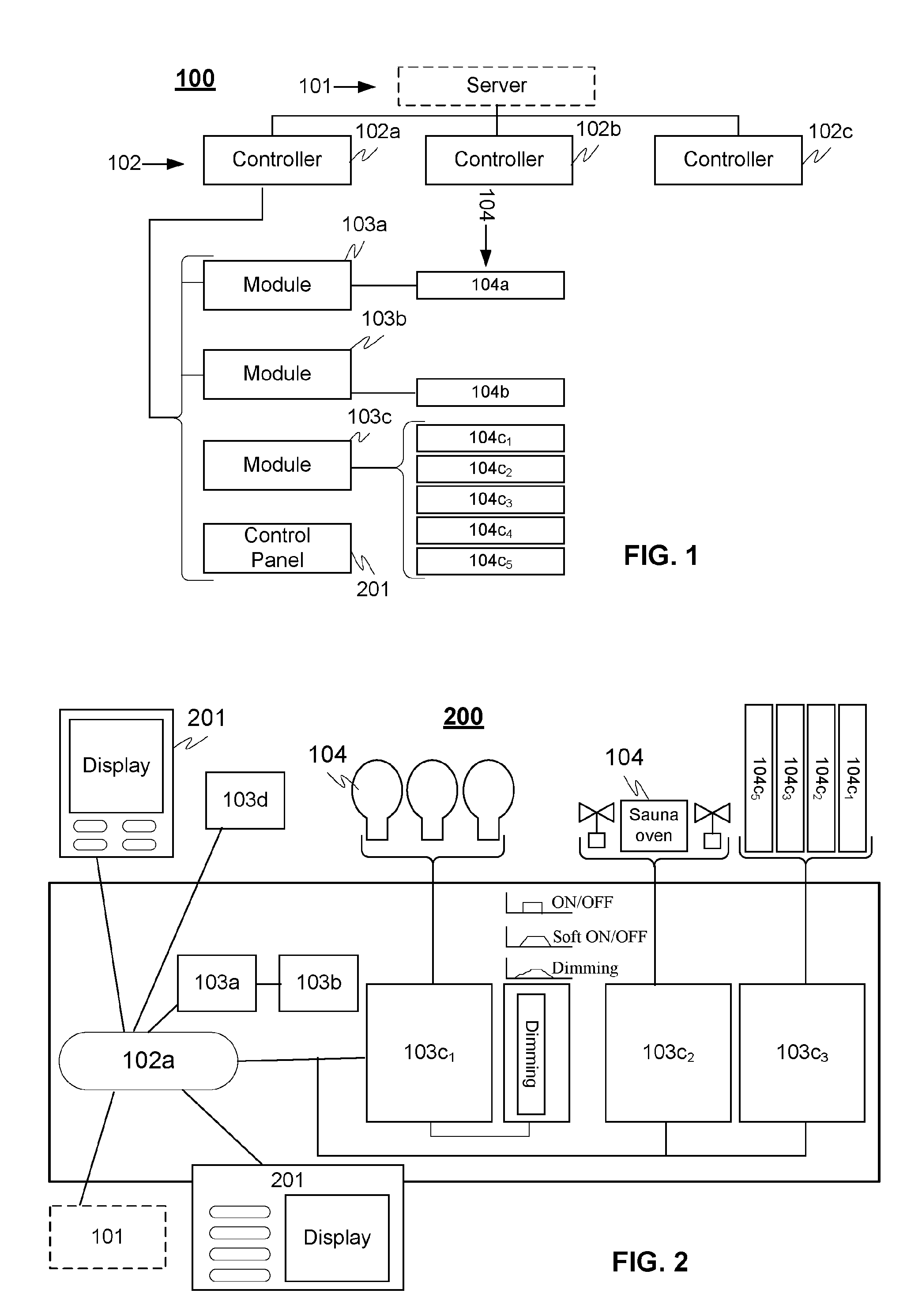
[0033]FIG. 1 illustrates an exemplary hierarchy of a system 100 in which a control panel according to the invention is used. The system advantageously comprises two layers, namely a controller layer having controlling means or shortly controllers 102 and a module layer having modules 103. In addition the system may also have a server layer 101 having e.g. a main server, but it should be noted that the main server or server layer is not essential in every embodiment according to the invention, but the controlling means may be in data communications directly with each other without the need of server between.

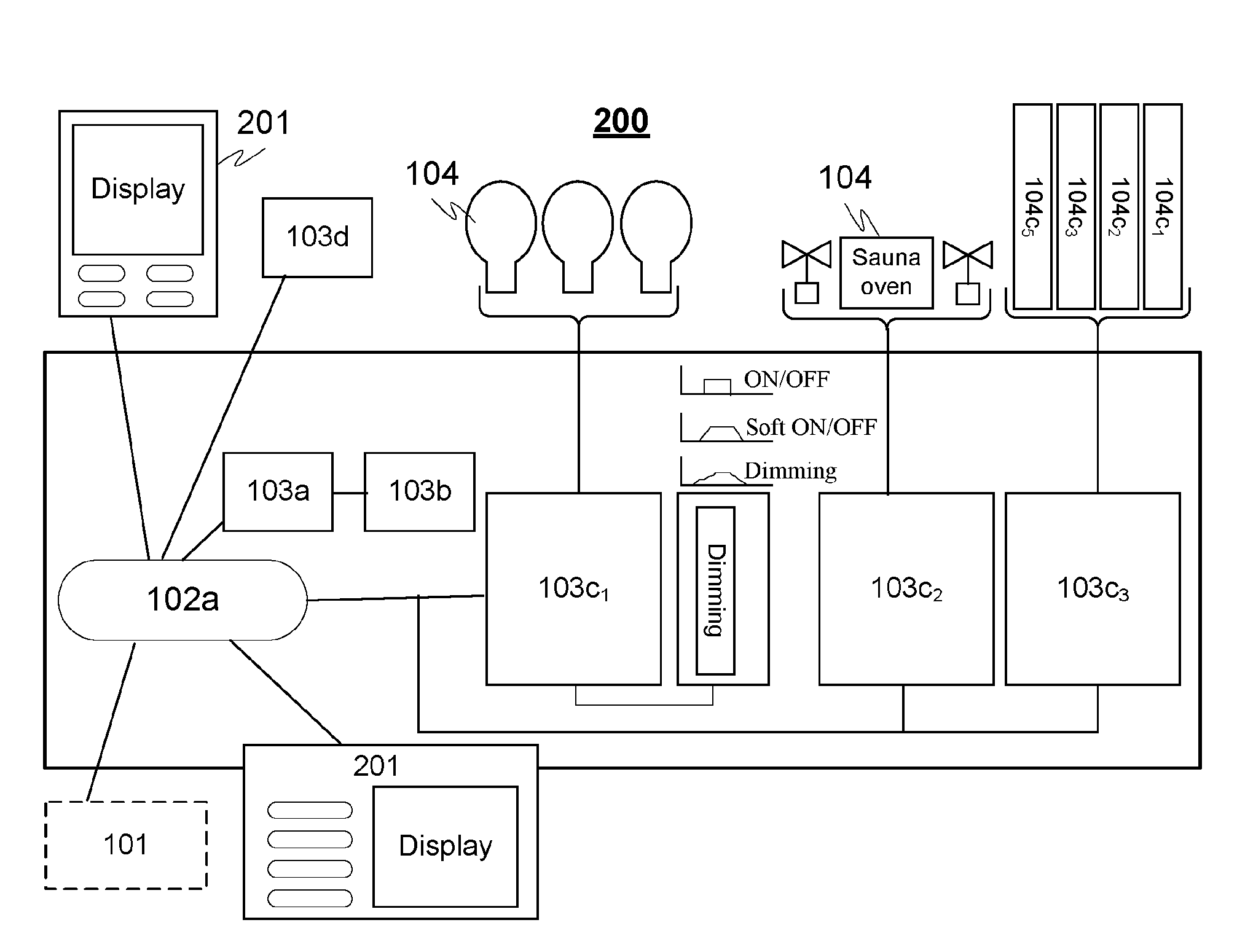
[0034]According to an embodiment one controller 102a is advantageously related to one entity, such as an apartment, home, business office, factory or logistics...


PUM


Abstract

The invention relates to a control panel and controlling system for adjusting environmental conditions of at least one location, wherein the location has desired environmental conditions. The system comprises equipments controlled by controlling means for changing and / or maintaining the environmental condition of the locations. The controlling means is adapted to provide controlling parameters to equipments for adjusting the environmental condition of said location. The system includes a control panel including at least one sensor, whereby the environmental condition is controlled on the basis of the signal received from the sensor.

Description

TECHNICAL FIELD OF THE INVENTION[0001]The present invention relates to a control panel for a control system and a control system. The invention especially relates to control systems for controlling environmental conditions of different entities, such as rooms. The environmental conditions may relate e.g. temperature, humidity, CO2 level, electricity, access rules, water supply, and lighting, for example.BACKGROUND OF THE INVENTION[0002]An average household annually uses approximately 13 MWh of energy only for heating the premises. In addition, all those households generate approximately ⅕ of global CO2 emissions. Operating costs (including energy costs) for the building can make up 80% of the total cost of ownership during a building's lifecycle. Thus it is especially important to invest in energy efficiency, with today's rising energy prices, to save on future operating costs.[0003]In order to save energy and to improve living environment in buildings, there are control systems for...

Claims


Application Information

Patent Timeline
Patent Type & Authority Applications(United States)
IPC IPC(8): G05B15/02
CPCG05B2219/2642G05B19/409G05B15/02
Inventor RAESTIK, RAIVOVIMBERG, PRIIT
Owner ZEROGROUP HLDG
Why Eureka
Try Eureka