Measuring device electronics for a measuring device as well as measuring device formed therewith

Active Publication Date: 2012-12-06
ENDRESS HAUSER FLOWTEC AG
View PDF8 Cites 6 Cited by
  • Summary
  • Abstract
  • Description
  • Claims
  • Application Information

AI Technical Summary

Benefits of technology

[0012]Taking the above into consideration, an object of the invention is to improve methods for testing measuring devices of the type being discussed, especially such generating measured values for chemical or physical measured variables based on a time (e.g. travel time) and/or frequency or phase angle measurement, respectively, to improve measuring device electronics of such measuring devices, with the goal that s

Problems solved by technology

A disadvantage of such a method for testing measuring device electronics is particularly to be seen in the fact that, for its performance, normal measuring operation of the measuring device must be interrupted, and consequently the portion of the

Method used


Image

  • Measuring device electronics for a measuring device as well as measuring device formed therewith
  • Measuring device electronics for a measuring device as well as measuring device formed therewith
  • Measuring device electronics for a measuring device as well as measuring device formed therewith

Examples


Example

DETAILED DESCRIPTION IN CONJUNCTION WITH THE DRAWINGS

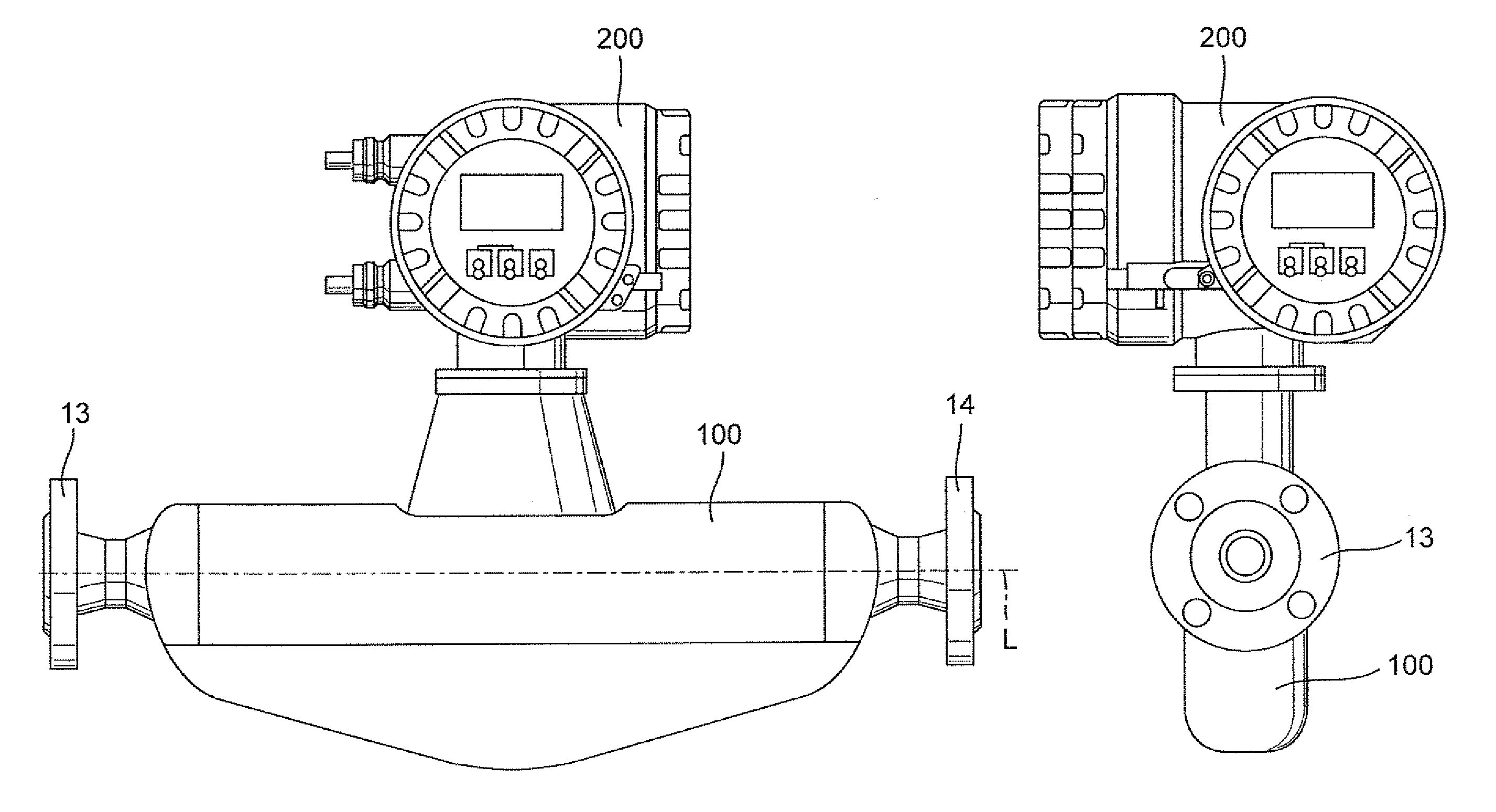
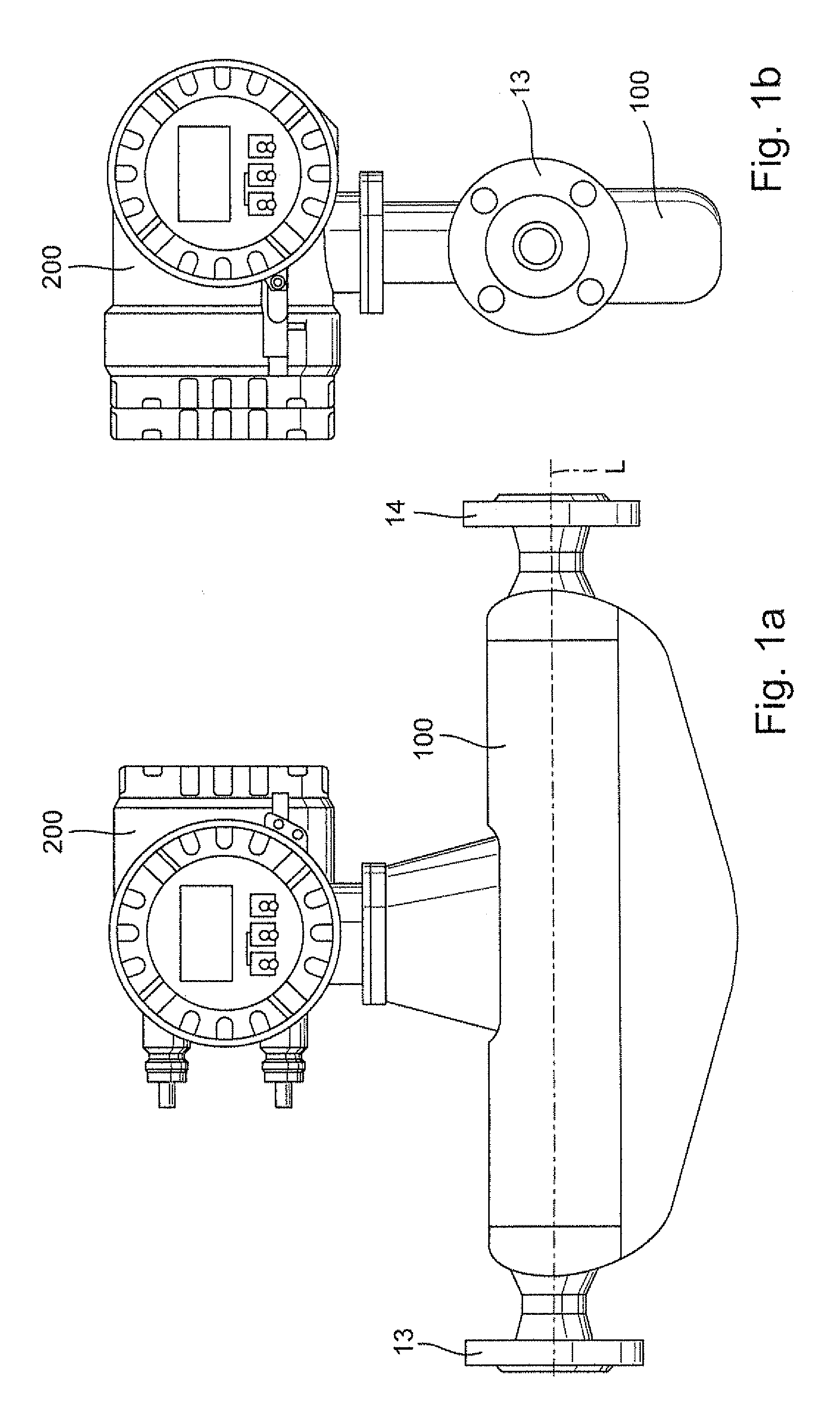
[0043]FIG. 1 shows schematically an example of an embodiment of a measuring device especially suited for application in industrial measurements and automation technology. The measuring device serves to measure at least one physical and / or chemical, measured variable of a medium, such as, for instance, a powder, a low viscosity liquid, a high viscosity paste and / or a gas, etc., conveyed in a medium transporting line, such as, for instance, a pipeline or a flume, or containable in a container, such as, for instance, a tank or a flume, and can be implemented, for example, as shown here, as an in-line measuring device, namely a measuring device insertable into the course of a pipeline (not shown). The measured variable can accordingly be, for example, a mass flow rate or a totaled mass flow of a medium flowing in a pipeline, a medium such as, for instance, a liquid, a powder, a gas, etc., or can also be, for example, a fill level of a...


PUM


Abstract

A measuring device electronics comprises a processor and two clock signal generators. One clock signal generator serves for producing a working clock signal, and also for producing a reference clock signal which is dependant on the working clock signal. The other clock signal generator, serves for producing a second reference clock signal, which is independent of the working clock signal. Based on the two independent reference clock signals, a frequency difference, can, to the extent that such is present, be ascertained during operation of the measuring device electronics or of the measuring device formed therewith. The frequency difference, represents a difference between the instantaneous clocking frequency of the first reference clock signal and the instantaneous clocking frequency of the second reference clock signal, and, in this respect, represents a measure for a deviation of an instantaneous clocking frequency, from the nominally predetermined clocking frequency, of the working clock signal.

Description

CROSS-REFERENCE TO RELATED APPLICATION:[0001]This application is a nonprovisional which claims the benefit of U.S. Provisional Application No. 61 / 491,420, filed on May 31, 2011.TECHNICAL FIELD[0002]The invention relates to a measuring device electronics for a measuring device (especially a measuring device embodied as a measuring and / or switching device of industrial measurements and automation technology and / or an electronic measuring device) as well as to such a measuring device. Moreover, the invention relates to a method for verifying such a measuring device.BACKGROUND DISCUSSIONS[0003]In industrial process measurements technology, especially also in connection with the automation of chemical processes or procedures for producing a product from a raw or starting material by the use of chemical, physical or biological processes and / or the automated control of industrial plants, electrical measuring devices installed near to the process, so called field devices, are applied, such ...

Claims


Application Information

Patent Timeline
IPC IPC(8): G04F8/04G01N31/00G06F19/00
CPCG01F1/8431G06F11/1604G01F1/8477G01F1/8436G06F11/1608
Inventor DRAHM, WOLFGANGENGSTLER, GERNOTPOHL, HANSMATT, CHRISTIANLALLA, ROBERTBRUDERMANN, MATTHIAS
Owner ENDRESS HAUSER FLOWTEC AG
Why Eureka
Try Eureka