Adjustment-free fill level sensor

Active Publication Date: 2016-10-13
VEGA GRIESHABER GMBH & CO
View PDF5 Cites 1 Cited by
  • Summary
  • Abstract
  • Description
  • Claims
  • Application Information

AI Technical Summary

Benefits of technology

[0015]In one embodiment of the invention, the arithmetic-logic unit is further configured to determine physical material properties by evaluating the at least two measurements. Primarily, the arithmetic-logic unit is configured to determine covering thickness. For this purpose, a physical parameter from the equation system to be solved can be eliminated without explicitly calculating it, for example. However, it may also be calculated and stored on a storage unit, for example for further uses. It may also be conveyed via a transceiver unit to a central evaluation point, for example in safety-critical systems for verifying the medium or the relevant medium parameters.
[0016]In a further embodiment of the invention, the measuring instrument further comprises a passive guard or shield, which is configured to largely block out the adhesion from the volume region monitored by the first sensor element, and which is additionally configured to detect the influence of the covering and/or adhering medium as a second sensor element and to actively evaluate it by way of the arithmetic-logic unit.
[0017]In a further embodiment of the invention, the guard is a guard electrode which serves to improve the measurement in the case of an impedance measurement and to largely block out undesirable regions close to the surface from the volume region monitored by the first measuring electrode, and which is additionally configured to detect the influence of the covering and/or adhering medium as a second electrode and to actively evaluate it by way of the arithmetic-logic unit.
[0018]In a further embodiment of the invention, in addition to the at least two sensor elements the measuring instrument further comprises a passive guard, which is configured to largely limit the volume region monitored by the relevant sensor elements to the region located in front of the sensor surface, in other words the region

Problems solved by technology

Information regarding physical properties of the medium is generally not automatically available to the sensor.
These situations may lead to incorrect measurements or imprecisions.
One reason for this is t

Method used


Image

  • Adjustment-free fill level sensor
  • Adjustment-free fill level sensor
  • Adjustment-free fill level sensor

Examples


Example

[0039]The drawings are schematic and not to scale.

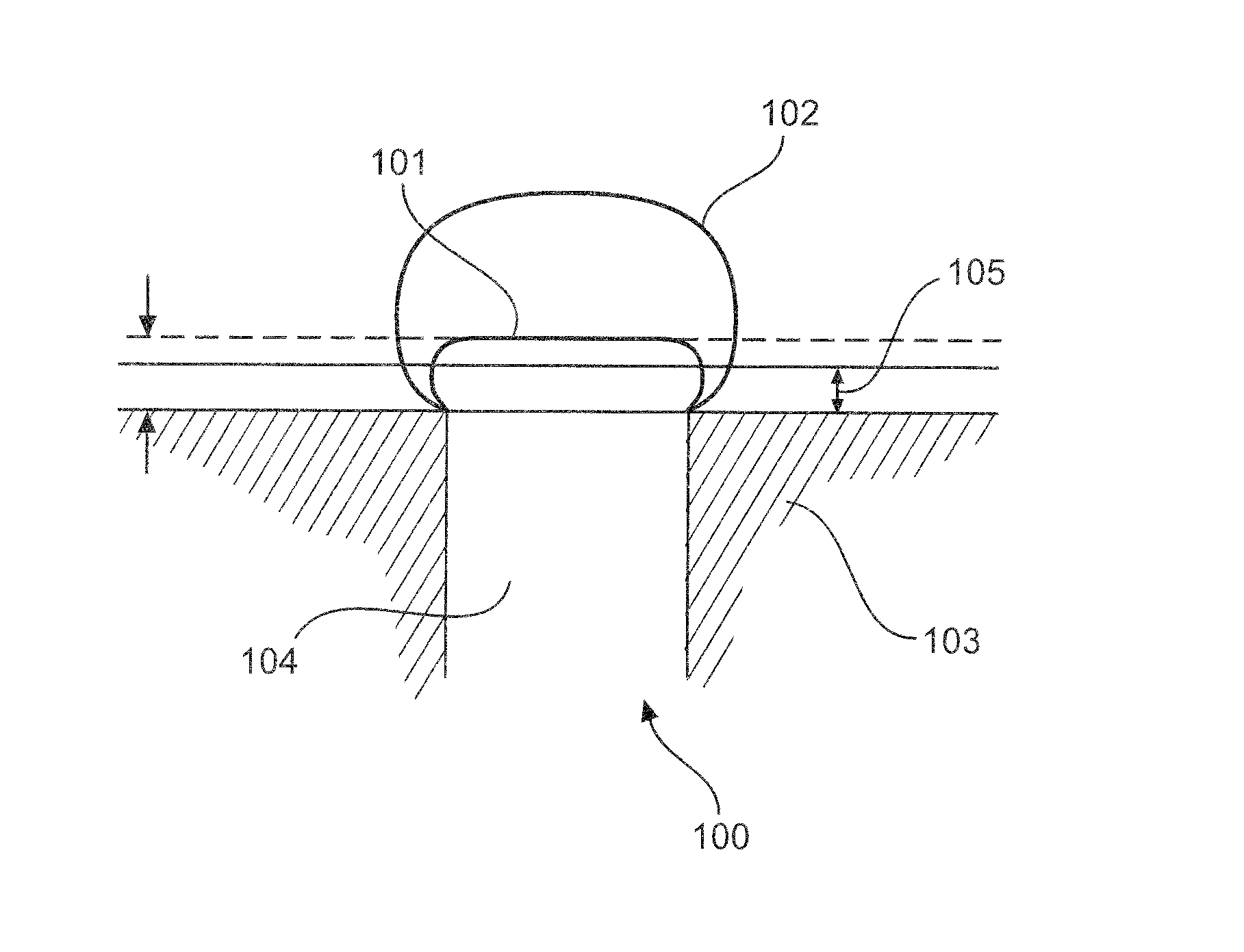
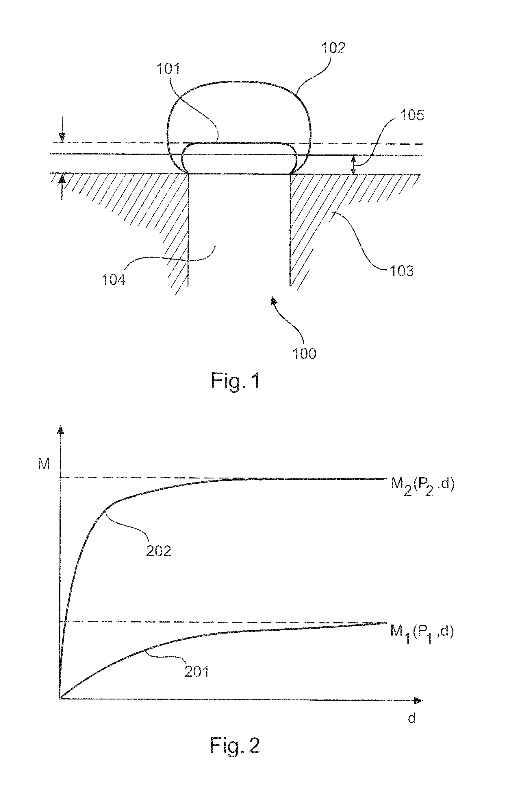
[0040]FIG. 1 shows an embodiment of a measuring instrument 100 for detecting media, in particular a limit level measuring instrument, comprising a sensor unit 104. This measuring instrument 100 is configured to make a switching decision, which is largely independent of the value of the physical substance property and remains constant, as to whether the limit level has been reached, without any user input regarding the physical substance properties being required. This switching decision is thus merely dependent on the pre-established covering thickness 105. This is achieved in that the sensor 104 installed in the container 103 takes at least two measurements (the measurements may be separated for example in time or in space). The first measurement evaluates a region 101 close to the surface and the second evaluates a volume region 102 extending further into the depth.

[0041]FIG. 2 shows two different measurement curves which are obtai...


PUM


Abstract

A measuring instrument for detecting a fill level or a limit level of a medium, for example fill levels in containers or chambers, is provided. The measuring instrument includes a sensor unit, which takes at least two measurements at two different penetration depths in the medium. For this purpose, an arithmetic-logic unit makes calculations so as to distinguish complete covering of the sensor unit by a medium from adhesion of parts of the medium to the sensor unit, using the results of the measurements.

Description

REFERENCE TO RELATED APPLICATIONS[0001]This application claims the benefit of the filing date of European Patent Application Serial No. 15 162 633.0 filed on 7 Apr. 2015, the disclosure of which is hereby incorporated herein by reference.FIELD OF THE INVENTION[0002]The invention relates to a measuring instrument for detecting a fill level or limit level of a medium, as well as to a method for detecting a fill level or limit level of a medium, to a program element and to a computer-readable medium.BACKGROUND[0003]Level sensors are used for example to measure the fill height or level of a medium in a container. Information regarding physical properties of the medium is generally not automatically available to the sensor. In particular, the permittivity or electrical conductivity may be of interest. The permittivity, also known as dielectric conductivity, specifies the “permeability” of a medium to electric fields. The electrical conductivity is inversely proportional to the electrical...

Claims


Application Information

Patent Timeline
IPC IPC(8): G01F23/00G01F23/296G01F23/26G01F23/24G01N9/36G01N15/08
CPCG01F23/0069G01N9/36G01F23/296G01F23/263G01F23/24G01N15/082G01F23/22G01F23/265G01F23/268G01F23/2961G01F23/2962G01N29/07G01N2291/02836G01N2291/045G01F23/80G01F23/804G01F25/20G01F23/802
Inventor DIETERLE, LEVIN
Owner VEGA GRIESHABER GMBH & CO
Why Eureka
Try Eureka