Apparatus and method for determining battery/cell's performance, age, and health

a battery/cell performance and age-related technology, applied in the direction of instruments, material analysis, measurement devices, etc., can solve the problems of complex, expensive and complicated instrumentation, lack of straightforward, intuitive interpretation of the response signal, and limited impedance information, so as to achieve quick and concise evaluation of the condition

Inactive Publication Date: 2012-12-06
REDEY LASZLO
View PDF0 Cites 53 Cited by
  • Summary
  • Abstract
  • Description
  • Claims
  • Application Information

AI Technical Summary

Benefits of technology

[0015]A particular object of the invention is to provide a solution allowing a quick and concise evaluation of the con

Problems solved by technology

Disadvantages of this method include the need for sophisticated, complicated and usually expensive instrumentation and the lack of a straightforward, intuitive interpretation of the response signal.
The impedance information is limited owing to

Method used


Image

  • Apparatus and method for determining battery/cell's performance, age, and health
  • Apparatus and method for determining battery/cell's performance, age, and health
  • Apparatus and method for determining battery/cell's performance, age, and health

Examples


embodiment 1

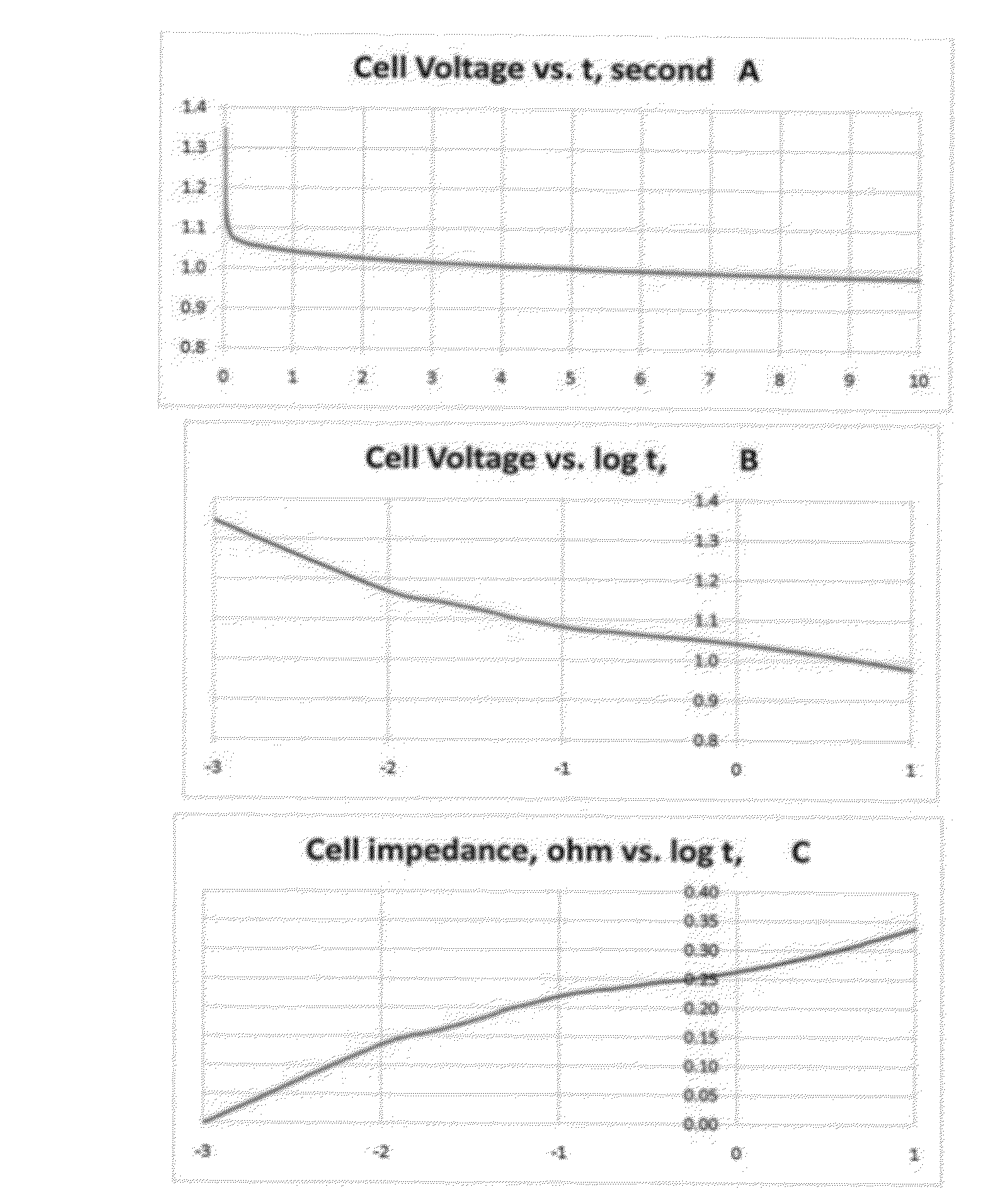
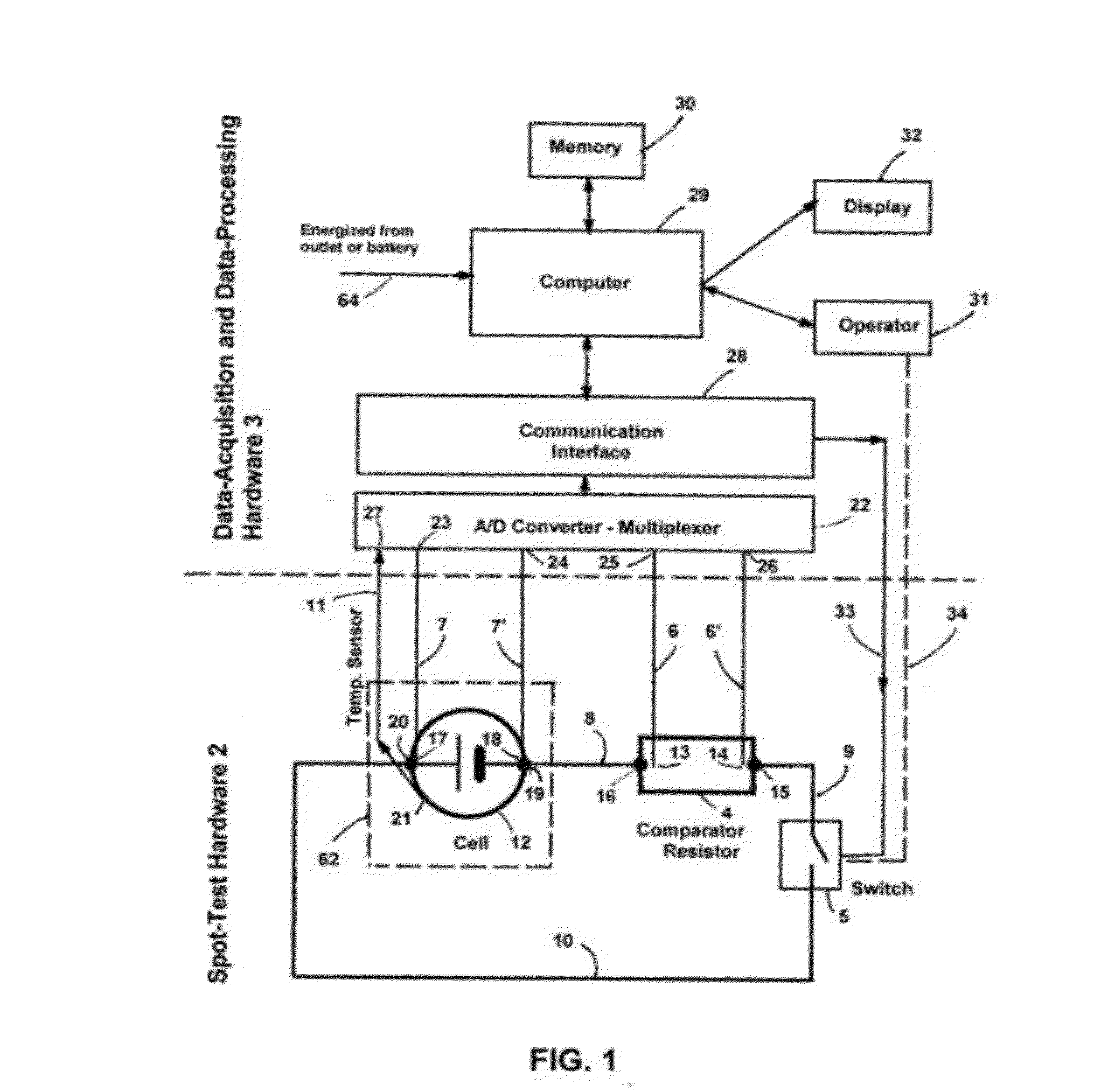
[0202]A typical basic embodiment of the measuring apparatus 1 is illustrated in FIG. 1. Two basic components of the invented apparatus 1 are a test circuit named spot-test hardware 2 (STH 2) and a data-acquisition and data processing hardware 3 (DPH 3) as shown in FIG. 1. Hardware 2 and data-processing hardware 3 are shown separated by a broken line. Hardware 2 and 3 works interactively with each other, and cell 12 and operator 31. Hardware 2 and hardware 3 are enclosed in (a) either a common case (not shown in FIG. 1, being a common practice and obvious) or (b) hardware 2 is in a case and hardware 3 components are commercial items.

Spot-Test Hardware 2 (STH 2)

[0203]Spot-test hardware 2 (FIG. 1) includes a comparator resistor 4, an on-off switch 5, current-carrying connecting cables 8, 9, and 10, a pair of voltage-measuring twisted leads 6 and 6′ connected to comparator resistor 4, a pair of voltage-measuring twisted leads 7 and 7′ used to measure voltage of a cell to be tested, and ...

embodiment 2

[0238]Embodiment 2 of the invention is shown in FIG. 2. Embodiment 2 is a general setup designed to carry out various spot test measurements such as STs 66, STpd 67, and MTD 77 generation. Using Embodiment 2, several ST measurements can be combined together due to the plurality of resistors (by number and resistance) included in selector switch 37.

[0239]In addition to components shown in FIG. 1, apparatus 1 includes a selector switch 37. Selector switch 37 consists of a resistor set 38 and a contact selector 42. Resistors RA 39, RB 40, and short 41 are connected to the circuit alternatively by contacts 43, 44, and 45, respectively. RA and RB are load resistors used to set certain current loads defined by C-rates. For example, to cover a 0.1 C to 10 C range. Comparator resistor 4 has the same function as in Embodiment 1.

[0240]For an STpd 67 test, the numerical value of RA is selected so that the sum of the resistances (39, 4, and cables) set an approximately 0.1 C-rate current. RB an...

embodiment 3

[0242]Embodiment 3 illustrates a discharge-charge spot test, STd-c 68. FIG. 3 shows the apparatus used for embodiment 3. In addition to components shown in FIGS. 1 and 2, hardware 2 includes a charger 46, a discharge-charge switch 47, connecting cables 48, 49, and 50, control leads 51 and 52. Charger 46 is usually a regular commercial charger specified to the type of cell 12. However, chargers may introduce electrical noise problems and somewhat distort the test cell's own charge stress response. To eliminate this problem, a charger battery-cell may be used as a charger. If a charger cell (at position 46) is used, it should have, preferably a 5-times higher rated capacity and a 0.5 V or a somewhat higher voltage than those of the test cell. The high capacity of the charger cell and, consequently, relatively low (negligible) power-domain impedance (vs the test cell) ensures that the measurement is valid for cell 12. The positive terminal of cell 12 and that of charger 46 or the alter...


PUM


Abstract

A self-energized measuring system for determining primary and secondary battery/cell's performance, age, and health by measuring and recording battery/cell's voltage response to a specified load-changing perturbation spot-test event. The cell's voltage response is compared to a synchronously measured voltage signal of a comparator resistor. The relationship between the two voltage signals is analyzed on logarithmic time scale to determine performance parameters such as cell impedance and power and their variation in the time domain. The cell temperature is also measured for impedance and power normalization for 20 centigrade. Results are compared to a previously generated master data tabulation characteristic of a similar, new cell of perfect health condition. The time-domain performance parameters are related to the performance, age and health of the cell at any particular instant. The evaluation method can be easily adjusted to various battery chemistries, types.

Description

[0001]The present application claims priority to provisional application Ser. No. 61 / 491,436, filed in the name of Laszlo Redey on May 31, 2011.BACKGROUND[0002]1. Field of Invention[0003]This invention relates to battery-cell-performance measuring apparatus and method. Particularly, to a self-energized measuring system used for determining primary and secondary battery / cell's performance, age, and health by measuring and recording battery / cell's voltage response to a specified load-changing perturbation spot-test event. The cell's voltage response is compared to a synchronously measured voltage signal of a comparator resistor. The relationship between the two voltage signals is analyzed on logarithmic time scale to determine time-domain performance parameters such as cell impedance and power and their variation in the time domain. The cell temperature is also measured and used for impedance and power normalization for the normal temperature of 20 centigrade. The spot-test results ar...

Claims


Application Information

Patent Timeline
IPC IPC(8): G01N27/416G06F19/00
CPCG01R31/3631G01R31/3679G01R31/3665G01R31/3651G01R31/378G01R31/367G01R31/392G01R31/386
Inventor REDEY, LASZLO
Owner REDEY LASZLO
Why Eureka
Try Eureka