
Application management system

a technology of application management and management system, applied in the field of application management system, can solve problems such as user requirements

Inactive Publication Date: 2012-12-06
XAGA NETWORK
View PDF10 Cites 13 Cited by
  • Summary
  • Abstract
  • Description
  • Claims
  • Application Information

AI Technical Summary

Benefits of technology

[0026]An application may use several data spaces and conversely one data space may contain several applications. This enables a high flexibility in the urbanization of an application, from the simplest to the most complex. The evolution of an application is much more easily managed by adapting the distribution of entities in spaces and the choices of an activation set.
[0054]This enables cross-referencing from several levels between entities of the same type. The management of an application is therefore more flexible. Multi-space management enables hierarchy couplings and therefore coupling between several different and personalized entities.

Problems solved by technology

A problem with this prior art is that the user is required to have technical computing knowledge to create and manage the application modules.

Method used


Image

  • Application management system
  • Application management system
  • Application management system

Examples


example 1

[0455]An intervening unit having only creation and modification rights at the N1P level for a “Request” object will be able to create a “Request” entity and modify the “Request” entities for which it is the issuer. It will not be able to access the requests for which it is not the issuer. In a non-limiting example, as seen previously, a “Request” entity comprises an Issuer field in which the administrator user U1 may enter the name of the “Request” entity issuer.

example 2

[0456]An intervening unit having reading rights at the N1S level for a “Project” object will be able to consult all the “Project” entities of the Department to which it belongs.

[0457]In a non-limiting example, a “Project” entity comprises a department field in which the administrator user U1 may enter the name of a Department that is responsible for the “Project” entity.

[0458]In a non-limiting example, an intervening unit is allocated to a department over a period via an intervening unit corresponding component (with management of validity dates of the intervening unit entities).

example 3

[0459]An intervening unit having reading rights only at the N1SF level for a “Task” object will be able to consult the tasks of requests connected to one of the subdepartments dependent on its department. In a non-limiting example, an intervening unit is allocated to a department over a period via an intervening unit corresponding component (with management of validity dates of the intervening unit entities). It will be automatically propagated to the subdepartments of this department. The same examples may be taken for a user profile PR.

[0460]Therefore, for the definition of first N1 and second N2 accreditation levels, in a non-limiting mode of embodiment, the administrator user U1 may utilize suitable interface elements UIe to:[0461]choose the data space D or Dc in which it wants to define the accreditation levels.[0462]Then, choose the user profile PR or an intervening unit according to which it wants to define the accreditations for a user profile or an intervening unit.[0463]Ch...


PUM


Abstract

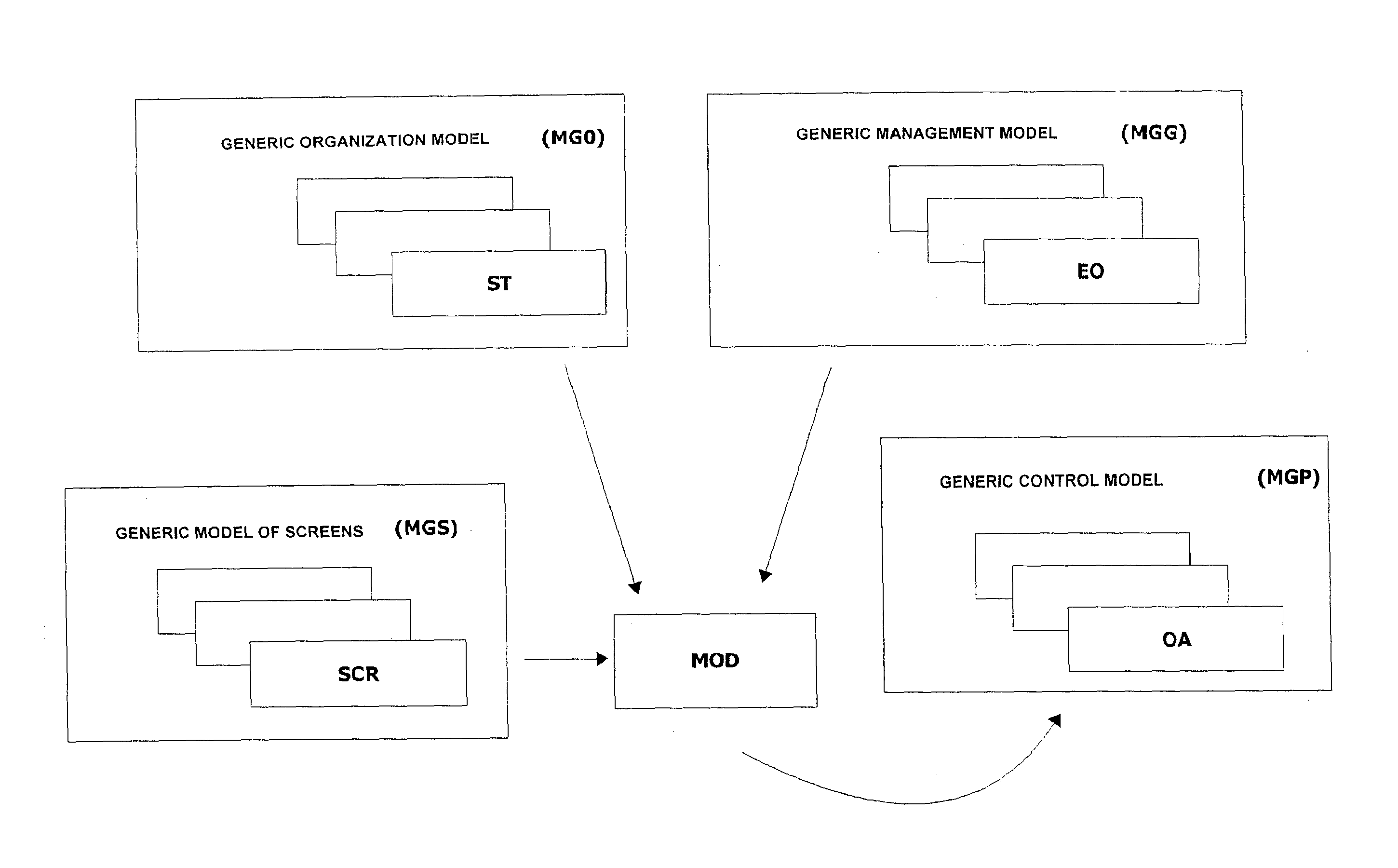
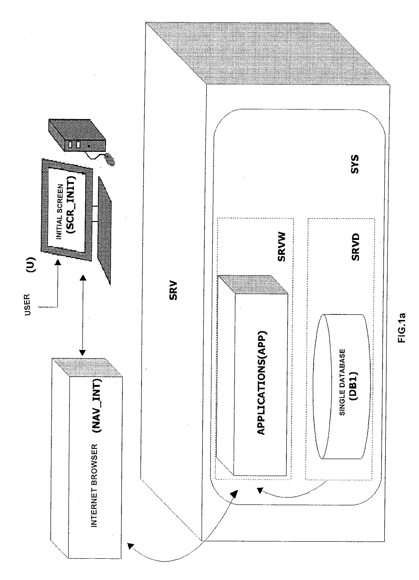
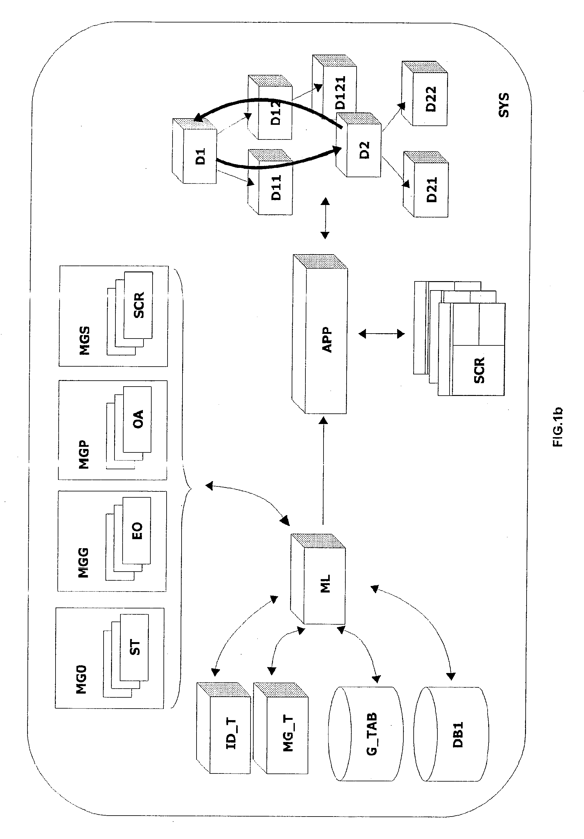
An application management system includes a web server including objects including a predefined and preassembled component, the objects forming: a generic organization model composed of logic organizational entities; a generic management model composed of logic operational entities; a generic control model composed of data analysis tools; a generic model of screens and kinematics for a user interface; a set of tables and files characterizing the activation and personalization options of the objects and the processes, streams and rules associated with the objects; tools for identifying possible activations of objects linked to an initial object activation; management tools for building logic networks including data spaces, and preassembled links that can be activated and personalized, each data space may be composed of all the objects, a connector object suitable for searching for tables and files; a data server including a single predefined physical database including data corresponding to the objects.

Description

TECHNICAL FIELD OF THE INVENTION[0001]The present invention relates to an application management system.PRIOR ART[0002]A known prior art for application management systems comprises a user interface to manage a plurality of applications, based on a plurality of application modules, said modules being based on a declarative computer programming language, for example in C++™ or JAVA™. For each application module, the user must declare, with said computer programming language, the attributes, functions, and links with other modules and events, that are associated with it. In general, these applications are present in the form of a software package dedicated to a predetermined recipient, for example the accountants in a company. Generic tools also exist that enable applications that also have a predetermined destination to be built.[0003]A problem with this prior art is that the user is required to have technical computing knowledge to create and manage the application modules. In addit...

Claims


Application Information

Patent Timeline
Patent Type & Authority Applications(United States)
IPC IPC(8): G06F9/44G06F21/62G06Q10/00
CPCG06F21/629G06Q10/06
Inventor XOUAL, YANNCIESLA, MARC
Owner XAGA NETWORK
Learn More