Liquid crystal display device and liquid crystal display method

Inactive Publication Date: 2012-12-13
SHARP KK
View PDF14 Cites 9 Cited by
  • Summary
  • Abstract
  • Description
  • Claims
  • Application Information

AI Technical Summary

Benefits of technology

[0028]This yields an effect of preventing a deterioration in display quality by reducing a variation between a lumin

Problems solved by technology

However, such a color display device causes the following problem: Merely simple division of one (1) frame into three frames corresponding to respective R, G, and B image signals i

Method used


Image

  • Liquid crystal display device and liquid crystal display method
  • Liquid crystal display device and liquid crystal display method
  • Liquid crystal display device and liquid crystal display method

Examples


Embodiment Construction

[0044]An embodiment of the present invention is specifically described below.

[0045]

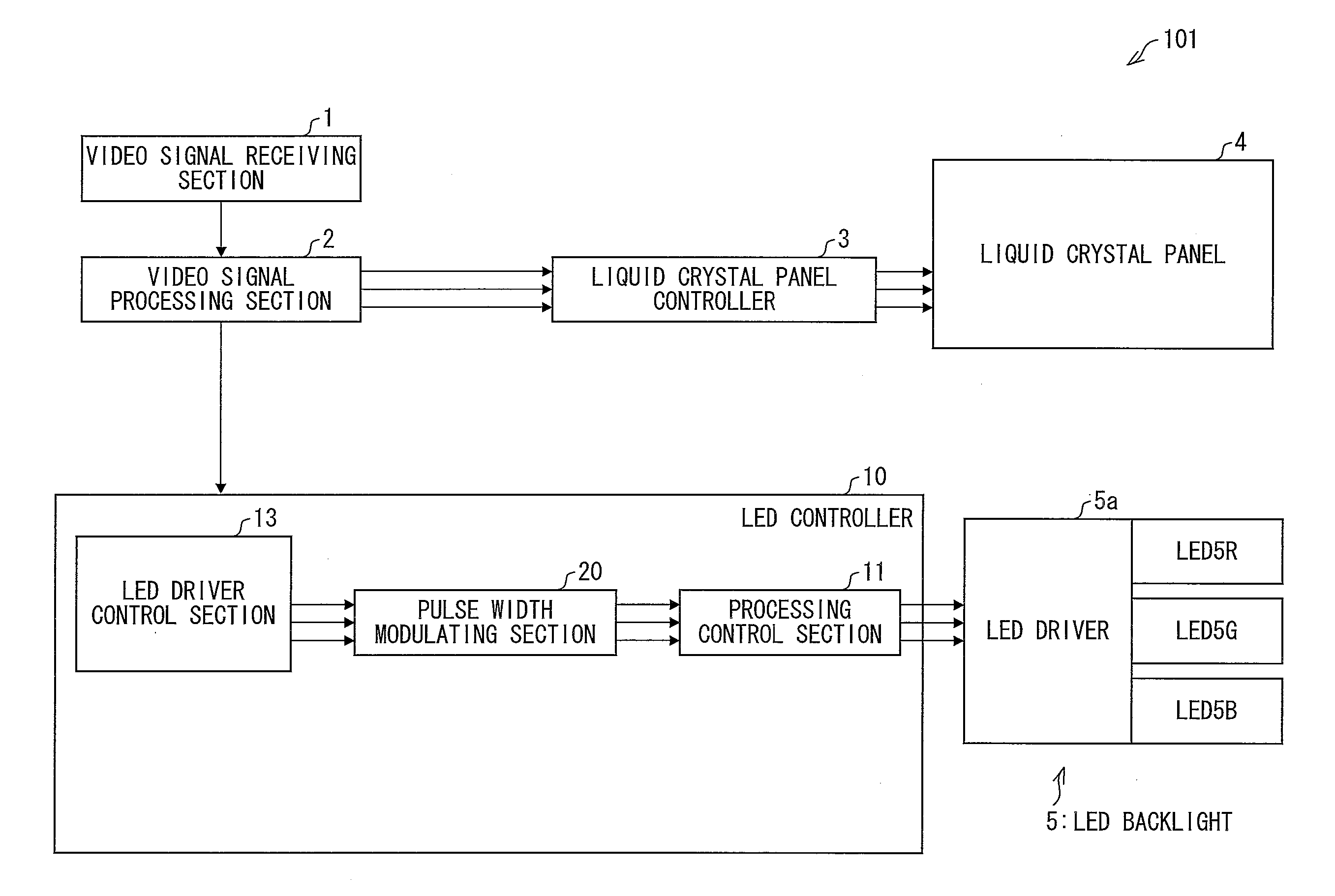
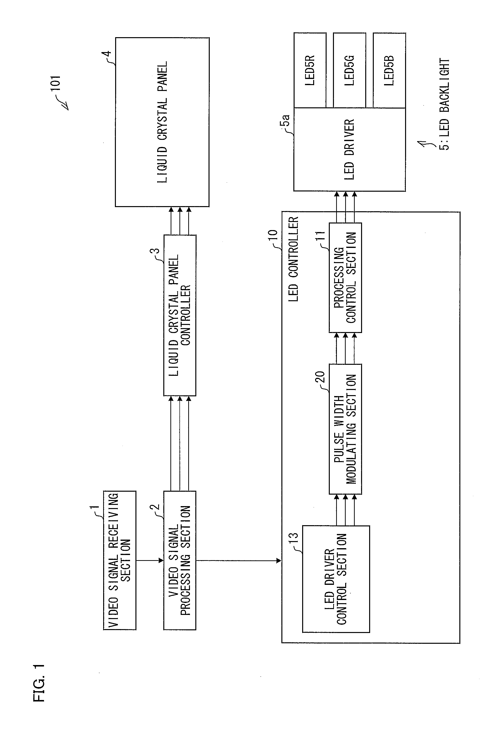
[0046]FIG. 1 is a block diagram showing an arrangement of the liquid crystal display device 101 of the present invention.

[0047]The liquid crystal display device 101 includes a video signal receiving section 1, a video signal processing section 2, a liquid crystal panel controller 3, a liquid crystal panel 4, an LED controller 10, and an LED backlight (Backlight) 5 (see FIG. 1). The LED controller 10 includes a process control section 11, a pulse width modulating section 20, and an LED driver control section (period dividing means) 13.

[0048]The liquid crystal panel 4 is a liquid crystal panel which includes no color filter.

[0049]The LED backlight 5 includes an LED (light source) 5R which emits red light as a first color, an LED (light source) 5G which emits green light as a second color, and an LED (light source) 5B which emits blue light as a third color. The LED backlight 5 further includes an LED dr...


PUM


Abstract

A liquid crystal display device (101) including a liquid crystal panel (4) and an LED backlight (5) which is provided with a plurality of LEDs (5R, 5G, and 5B) that emit light of different colors from a backside of the liquid crystal panel (4), the liquid crystal display device (1), in accordance with a video signal supplied thereto, (i) displaying a color image by controlling an aperture ratio of the liquid crystal panel (4) and luminances of the respective plurality of LEDs (5R, 5G, and 5B), and (ii) controlling the luminances of the respective plurality of LEDs (5R, 5G, and 5B) by pulse width modulation, the liquid crystal display device (101) includes: period dividing means (15) for dividing a frame of a video signal into a plurality of periods; and a pulse width modulating section (20) which generates a pulse signal for causing each of the plurality of LEDs (5R, 5G, and 5B) to emit light so that for each of the plurality of periods into which the period dividing means (15) has divided the frame, the plurality of LEDs (5R, 5G, and 5B) emit light while overlapping with each other. According to this, a deterioration in display quality is prevented by reducing a variation between a luminance ratio set in accordance with each frame and a luminance ratio of light transmitted through a liquid crystal panel.

Description

REFERENCE TO RELATED APPLICATIONS[0001]This application is a national stage application under 35 USC 371 of International Application No. PCT / JP2010 / 072399, filed Dec. 13, 2010, which claims the priority of Japanese Patent Application No. 2010-079575, filed Mar. 30, 2010, the entire contents of which are incorporated herein by reference.FIELD OF THE INVENTION[0002]The present invention relates mainly to a liquid crystal display device employing a field sequential method.BACKGROUND OF THE INVENTION[0003]In general, many of color display devices such as a television receiver and a computer monitor as an image display device which is capable of color displaying, displays an image by a color mixing method called an additive color mixture, using three primary colors, i.e., red, green and blue.[0004]Currently, a common color display device uses color filters which are colored in R (red), G (green), and B (blue), so as to perform a color display.[0005]Meanwhile, a color display device has ...

Claims


Application Information

Patent Timeline
IPC IPC(8): G09G3/36
CPCG09G3/3413G09G2320/064G09G2310/0235
Inventor GOTOH, TOSHIYUKI
Owner SHARP KK
Why Eureka
Try Eureka