
Left/right rearview device for a vehicle

Inactive Publication Date: 2012-12-13
CHO SUNG HO
View PDF58 Cites 35 Cited by
  • Summary
  • Abstract
  • Description
  • Claims
  • Application Information

AI Technical Summary

Benefits of technology

[0014]In consideration of the foregoing, the present disclosure provides a side-view and rearview apparatus for a vehicle which may be easily installed at the vehicle without deforming the appearance of the vehicle and may not take much installation effort and time, and may be easy for the driver to maintain and operate.
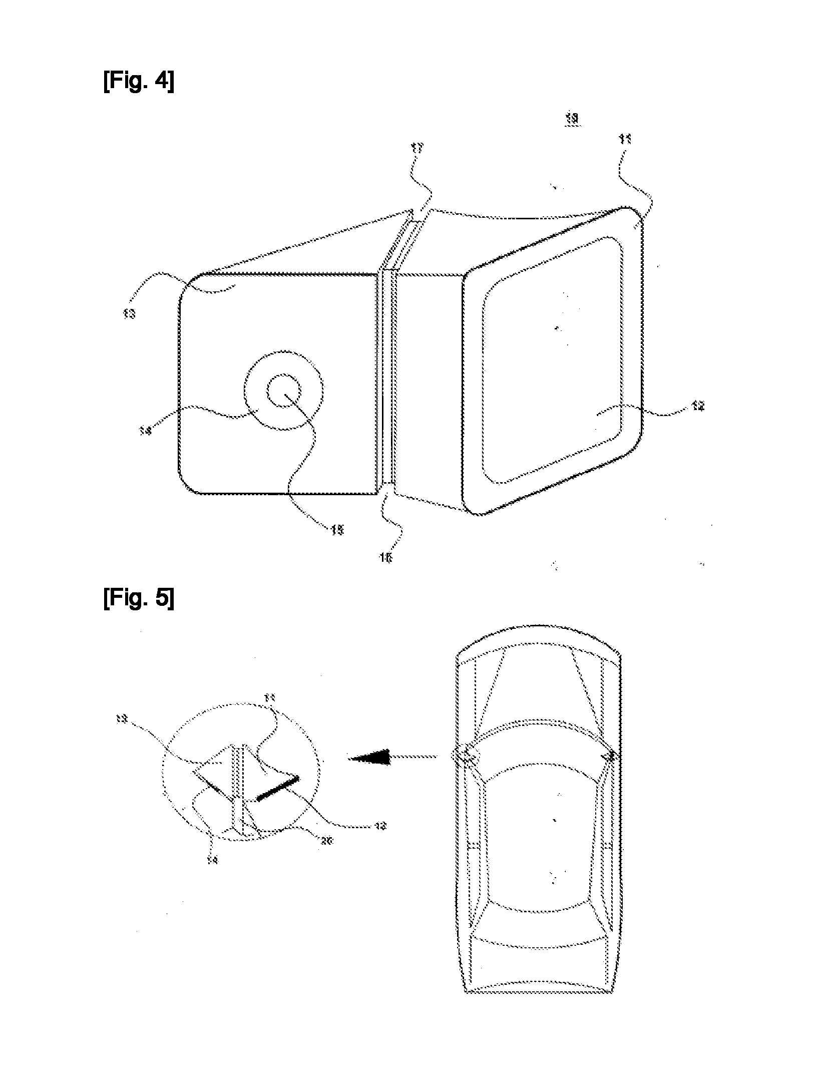
[0015]The present disclosure provides a side-view and rearview apparatus for a vehicle which may greatly improve sensing of the view around the vehicle using a camera and monitor and may be directly applied to a new vehicle or may be easily employed at the used vehicle by removing the rearview mirror and adding the same in place of the mirror. To this end, the present apparatus includes an integration of the monitor, the camera and a control unit to control them. This integration may be realized in one manner in which the monitor, the camera and the control unit are integrated into one body which in turn is shipped or distributed; and in the other manner in which camera and monitor housings, either thereof including the control unit, are separately shipped or distributed and then are fixed to a metal support plate 30 installed at a corner 100 in front of a glass of the front door.
[0016]The configuration of the present apparatus may be simple and thus any kind of the driver may easily learn installation, operation and maintenance thereof. Moreover, the present apparatus may provide an opportunity that the driver departs from keeping on seeing an area in front of the vehicle to slightly rotate his / her head toward left and / or right sides. This may avoid the driver from getting sleepy during drive.
[0024]In accordance with the present disclosure, the view angle for the driver may be enlarged with a maximum level by moving the camera housing (thus, changing a view direction of the camera) and the monitor housing (thus, changing a display direction of the monitor) in up-down, left-right and / or front-rear directions. Thus, the driver may secure a more wide-range view angle toward a side and rear around the vehicle compared to the conventional rearview mirror during drive, thereby achieving considerable drive safety improvement.
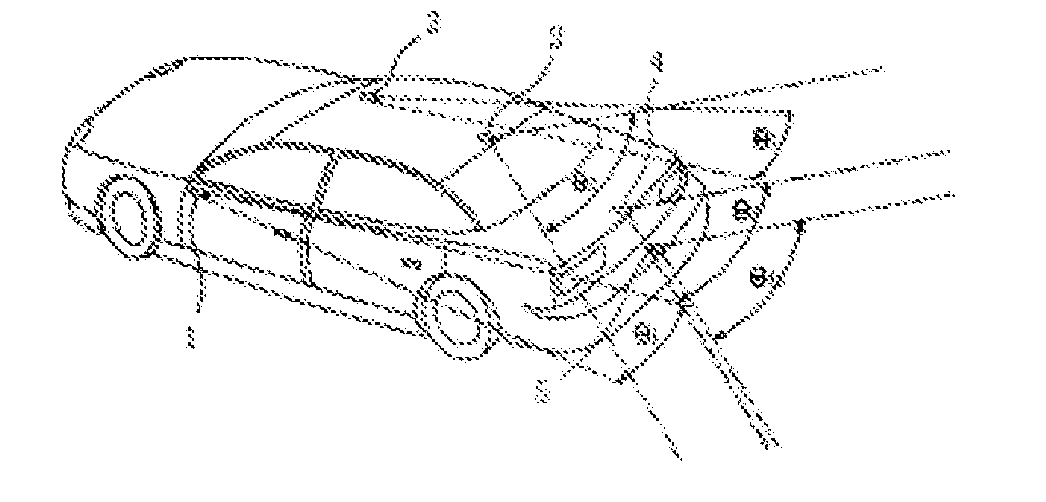
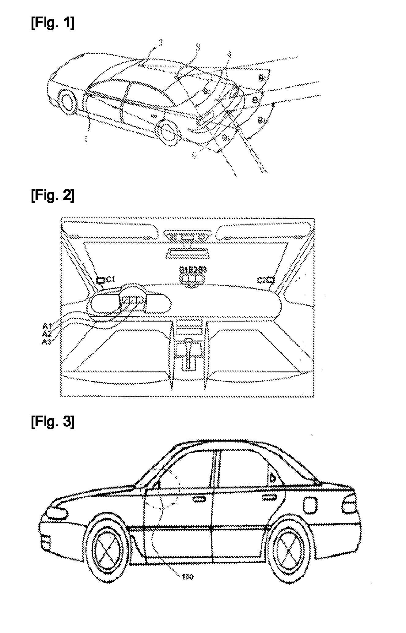
[0025]In accordance with the present disclosure, unlike the prior art side-view and rear-view sensing system as shown in FIG. 1, all of the components such as the camera, monitor and control unit are integrated into a single body which in turn is shipped; alternatively, the camera housing and monitor housing are separately manufactured and shipped and then are integrated with each other via a bolt and nut or via a metal support plate. Thus, the present apparatus may be simple and easy to install and maintain. Further, productivity thereof may improve.
[0026]In accordance with the present disclosure, unlike the prior art side-view and rear-view sensing system as shown in FIG. 1, the camera and monitor are adjacent to each other and hence only small amount or none of an electrical wire to connect them each other may be consumed, and necessary parts of the apparatus may be simplified and easy to assemble, leading to noticeable reduction of the product cost.

Problems solved by technology

However, for such conventional rearview mirrors, in order to see the left and right mirrors, the driver should spend a little time which otherwise may be used to see an area in front of the vehicle and also rotate his / her head toward the mirrors, frequently leading to car accidents.
Further, the rearview mirror has inherently a blind spot due to its physical limit.
Moreover, since the rearview mirror is located outside the vehicle, the rearview mirror may suffer from external water, humidity, dirt, frost, or the like, resulting in difficulty for securing the view around the vehicle.
However, such a side-view and rear-view sensing system may be problematic in that the plurality of the cameras should be installed at various locations outside of the vehicle and thus the vehicle frame should be deformed for installation of the cameras.
Further, since the plurality of the cameras installed at various locations and the monitor installed independently from the cameras as mentioned above should be connected with each other via electrical wires, the installation thereof may be difficult and time-consuming and need elaborate skills.
Further, since the cameras and monitor are located far from each other, not only the installation thereof may be difficult but also the maintenance thereof may take much effort.
Further, due to the complexity of the system, the driver should learn many kinds of functions and associated operation buttons, so that it takes much effort and time for the driver to be familiar and feel comfortable with the system and thus to be absorbed in driving the vehicle.
Such complexity of the system may cause un-safety and inconvenience for the vehicle depending on the driver type.
Further, using such a side-view and rear-view sensing system, the driver may keep on seeing only an area in front of the vehicle.
In this way, when the driver keeps on seeing only the same area during drive, the driver may easily get sleepy.
Therefore, using such a side-view and rear-view sensing system may lead to a car accident.

Method used


Image

  • Left/right rearview device for a vehicle
  • Left/right rearview device for a vehicle
  • Left/right rearview device for a vehicle

Examples


Embodiment Construction

[0035]Reference will now be made in detail to embodiments, examples of which are illustrated in the accompanying drawings. However, the present disclosure may be embodied in many different forms and should not be construed as limited to the embodiments set forth herein. Rather, these embodiments are provided so that this disclosure will be thorough and complete, and will fully convey the scope of the disclosure to those skilled in the art. The present disclosure is defined only by the categories of the claims. In certain embodiments, detailed descriptions of device constructions or processes well known in the art may be omitted to avoid obscuring the disclosure by a person of ordinary skill in the art. Wherever possible, the same reference numbers will be used throughout the drawings to refer to the same or like parts.

[0036]Spatially-relative terms such as “below”, “beneath”, “lower”, “above”, or “upper” may be used herein to describe one element's relationship to another element as...


PUM


Abstract

The present disclosure relates to a side-view and rearview apparatus for a vehicle which may be simply and conveniently employed in place of a conventional rearview mirror. In particular, the present disclosure relates to a side-view and rearview apparatus including a camera 14 to image a side-view and rearview around the vehicle; a monitor 12 to display the side-view and rearview from the camera; a control unit to enable the side-view and rearview from the camera to be displayed on the monitor; and a body 10 to accommodate the camera, monitor and control unit, the body being installed at a front portion of left and / or right front doors of the vehicle.

Description

CROSS-REFERENCE TO RELATED APPLICATION(S)[0001]This application claims the benefit of Korean Patent Application No. 2010-0016530, filed on Feb. 24, 2010 in the Korean Intellectual Property Office, the disclosure of which is incorporated herein by reference.BACKGROUND[0002]1. Field[0003]The present disclosure relates to a side-view and rearview apparatus for a vehicle which may be simply and conveniently employed in place of a conventional rearview mirror. In particular, the present disclosure relates to a side-view and rearview apparatus including a camera 14 to image a side-view and rearview around the vehicle; a monitor 12 to display the side-view and rearview from the camera; a control unit to enable the side-view and rearview from the camera to be displayed on the monitor; and a body 10 to accommodate the camera, monitor and control unit, the body being installed at a front portion of left and / or right front doors of the vehicle. The present apparatus is fixed at a corner 100 in...

Claims


Application Information

Patent Timeline
IPC IPC(8): H04N7/18
CPCB60R1/00B60R11/0235B60R11/04B60R2300/802B60R2001/1253B60R2300/106B60R2300/8046B60R1/28B60R1/26
Inventor CHO, SUNG HO
Owner CHO SUNG HO
Features
  • Generate Ideas
  • Intellectual Property
  • Life Sciences
  • Materials
  • Tech Scout
  • Unparalleled Data Quality
  • Higher Quality Content
  • 60% Fewer Hallucinations
Learn More