
Terminal box for solar cell module

Inactive Publication Date: 2012-12-13
SUMITOMO WIRING SYST LTD
View PDF5 Cites 9 Cited by
  • Summary
  • Abstract
  • Description
  • Claims
  • Application Information

AI Technical Summary

Benefits of technology

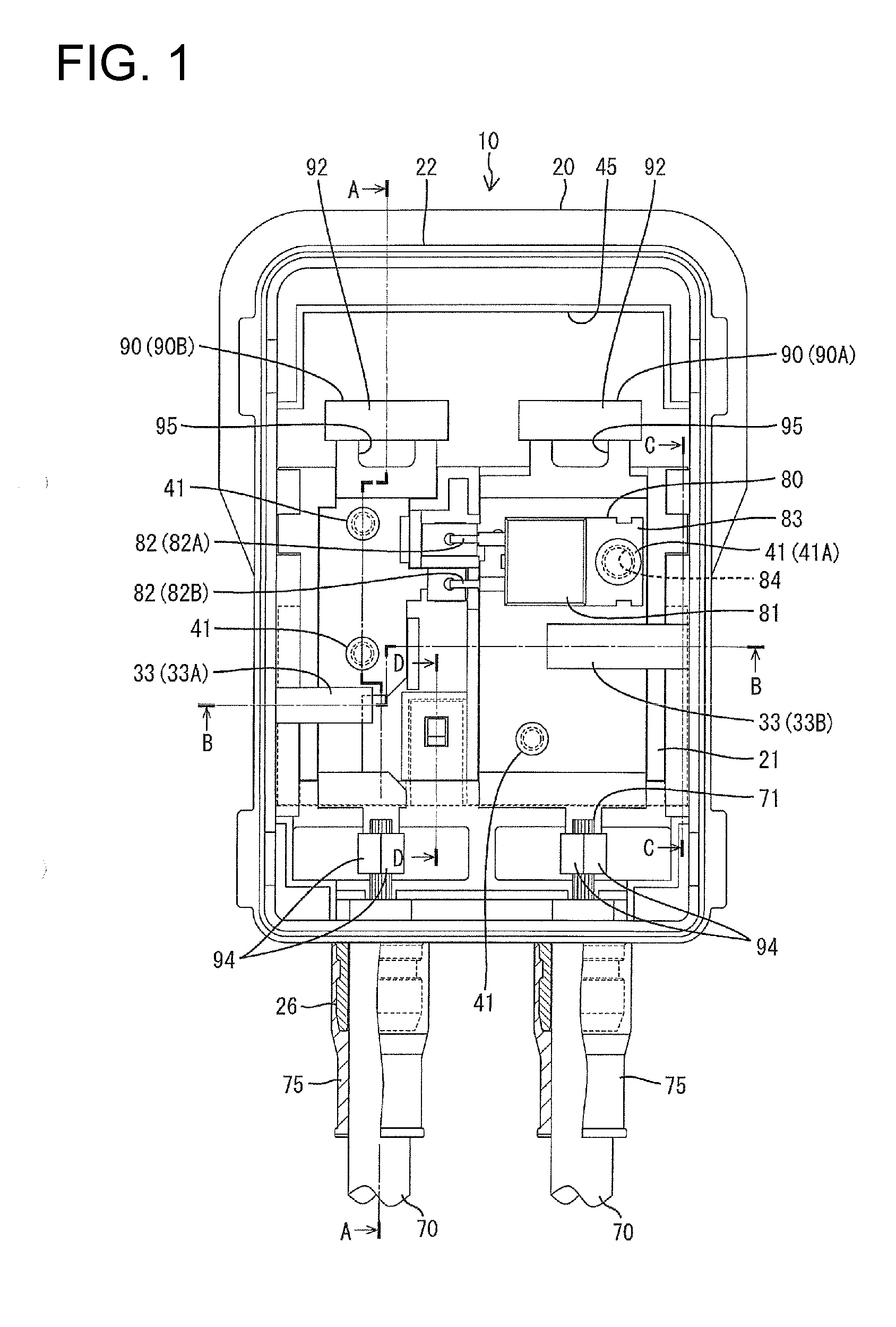
[0010]When the outer plate is mounted to the base plate, the pressing piece is arranged to be able to come into contact with the outer surfaces of the terminal plates, thereby preventing the lifting of the terminal plates. In this case, since the pressing piece is integrally formed to the outer plate, a cost increase is suppressed as compared with the case where the pressing piece is formed separately from the outer plate and the base plate. Further, since the outer plate has lower heat resistance than the base plate, in other words, the base plate has higher heat resistance than the outer plate, thermal damage of the base plate can be avoided even if the heating part of the rectifying element generates heat. Further, the outer plate not supporting the rectifying element is hardly thermally damaged, wherefore the deformation of the pressing piece is prevented. As a result, the lifting of the terminal plates can be reliably prevented by the pressing piece.
[0020]According to the present invention, it is possible to obtain a terminal box for solar cell module configured to suppress a cost increase and prevent the lifting of terminal plates.

Problems solved by technology

In the above conventional terminal box, the bottom wall may be possibly thermally damaged due to heat generation of the diode.
However, in this case, there has been a problem of increasing cost since the pressing plate is separately necessary.

Method used


Image

  • Terminal box for solar cell module
  • Terminal box for solar cell module
  • Terminal box for solar cell module

Examples


Embodiment Construction

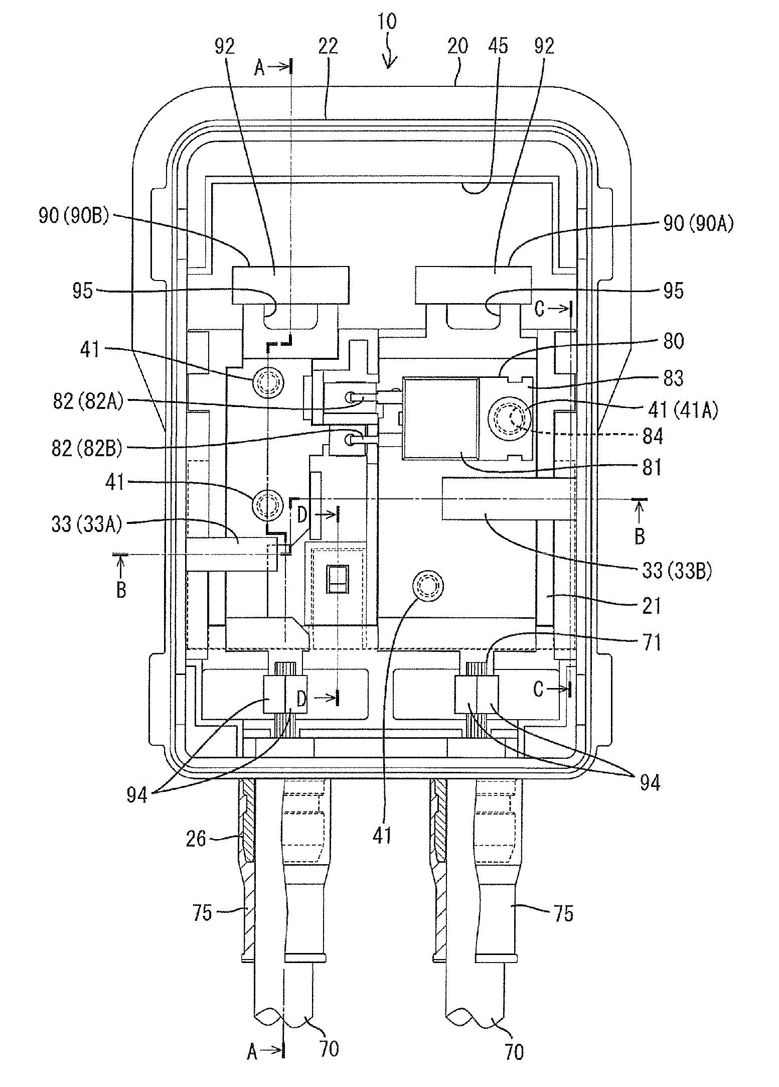
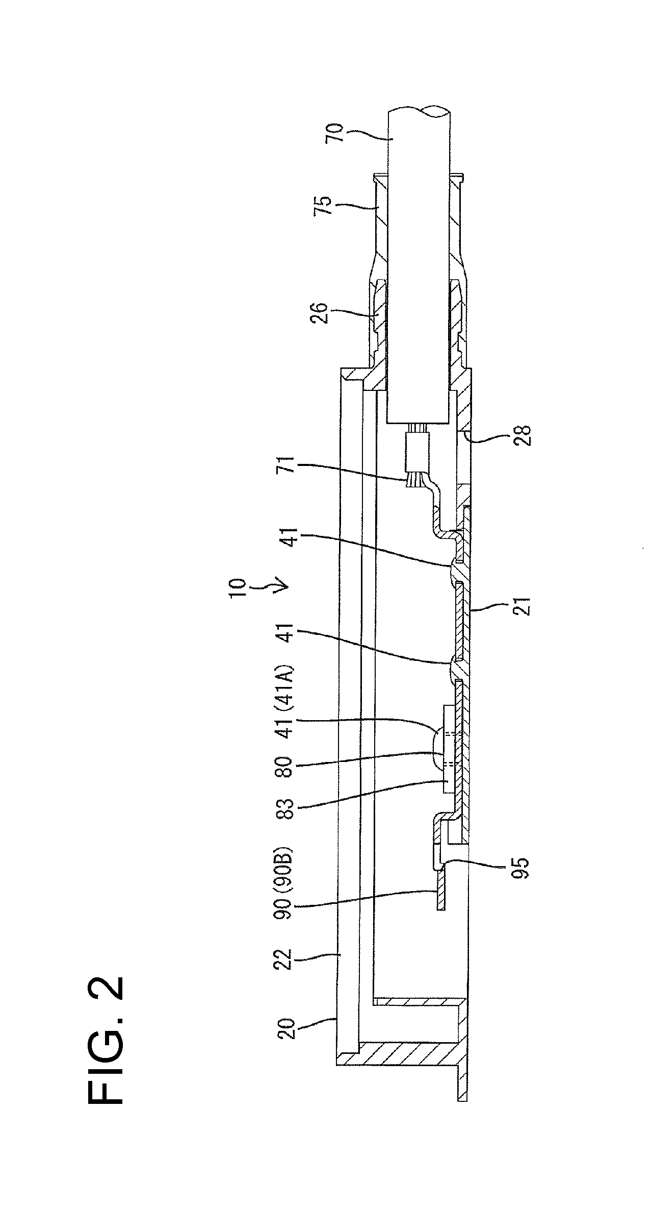
[0030]An embodiment of the present invention is described with reference to FIGS. 1 to 9. A terminal box for solar cell module (hereinafter, referred to as a terminal box 10) according to the embodiment includes a box main body 20, a plurality of terminal plates 90 and one bypass diode (which is a heating element and, hereinafter, referred to as a diode 80).

[0031]The box main body 20 is made of synthetic resin and in the form of a plate box as a whole and includes a rectangular base plate 21 and an outer plate 22 surrounding the base plate 21. The base plate 21 forms the bottom wall of the box main body 20 and the outer plate 22 forms the peripheral wall of the box main body 20. The base plate 21 is removably slid and mounted to the outer plate 22 to be fixed.

[0032]The outer plate 22 is in the form of a rectangular frame standing from a peripheral edge part of the base plate21 and includes a pair of left and right side walls 23 and front and rear walls 24, 25 as shown in FIG. 9. The...


PUM


Abstract

A terminal box (10) includes terminal plates (90), a base plate (21) for supporting the terminal plates (90) and an outer plate (22) surrounding the base plate (21). The base plate (21) has higher heat resistance than the outer plate (22) and is mounted and fixed to the outer plate (22). The outer plate (22) is formed integrally with pressing pieces (33) for preventing the lifting of the terminal plates (90) from the base plate 21 by being arranged to be able to come into contact with the outer surfaces of the terminal plates (90) as the base plate (21) is mounted.

Description

BACKGROUND OF THE INVENTION[0001]1. Field of the Invention[0002]The present invention relates to a terminal box for solar cell module.[0003]2. Description of the Related Art[0004]A terminal box for solar cell module (hereinafter, terminal box) disclosed in Japanese Unexamined Patent Publication No. 2009-302590 includes a plurality of terminal plates, a diode connected to two corresponding terminal plates, a bottom wall which supports the terminal plates and the diode and a peripheral wall which surrounds the bottom wall. The peripheral wall is integrally formed to stand from a peripheral edge part of the bottom wall. Further, the diode includes a heating body. When the heating body generates heat, this heat is radiated from the terminal plates toward a solar cell panel via the bottom wall.[0005]Resiliently deformable resilient locking pieces are integrally formed to stand on the bottom wall. In the process of placing the terminal plates on the bottom wall, the resilient locking piec...

Claims


Application Information

Patent Timeline
IPC IPC(8): H05K5/00
CPCH02S40/34Y02E10/50
Inventor YOSHIKAWA, HIROYUKIHIGASHIKOZONO, MAKOTO
Owner SUMITOMO WIRING SYST LTD
Learn More