Offset jaw suturing device, system, and methods

Active Publication Date: 2012-12-13
BOSS INSTR
View PDF16 Cites 15 Cited by
  • Summary
  • Abstract
  • Description
  • Claims
  • Application Information

AI Technical Summary

Benefits of technology

[0021]In another aspect, the method includes contacting a suturing needle at a first location along a plane of curvature of the needle with a needle contacting surface of a first clamp of a suturing device so as to position an axis of the needle at a desired alignment relative to the first clamp. The physician may the grasp a second location of the needle along a plane transverse to the plane of curvature of the needle between first and

Problems solved by technology

In particular, when suturing with a needle grasping tool, such as a needle holder, the needle may have a tendency to slip or pivot about the point at which the needle is grasped.
When suturing, it can be difficult to position a needle in precise alignment within the grasping tool, and even more difficult to maintain that alignment as the needle is subjected to various external forces during suturing.
The forces exerted on the needle by the tissue during penetration and the forces from the suture as it is pulled taught may cause misalignment of the needle within the tissue grasping tool.
This misalignment may interfere with the suturing process, which may be delayed as the physician realigns the needle with the needle grasping tool.
Another problem, is that when a needle become misaligned some physicians have a tendency to grab the needle with their hand to realign the needle, which can potentially lead to unnecessary contamination of tissues in the surgical environment and/or risks of the needle perforating through the glove and skin of the physician.
Moreover, realignment of the needle once misaligned is even more difficult in a minimally invasive environment where the surgeon typically relies on an endoscope or imaging procedures to correct needle alignment.
These difficulties may lead to increased fati

Method used


Image

  • Offset jaw suturing device, system, and methods
  • Offset jaw suturing device, system, and methods
  • Offset jaw suturing device, system, and methods

Examples


Embodiment Construction

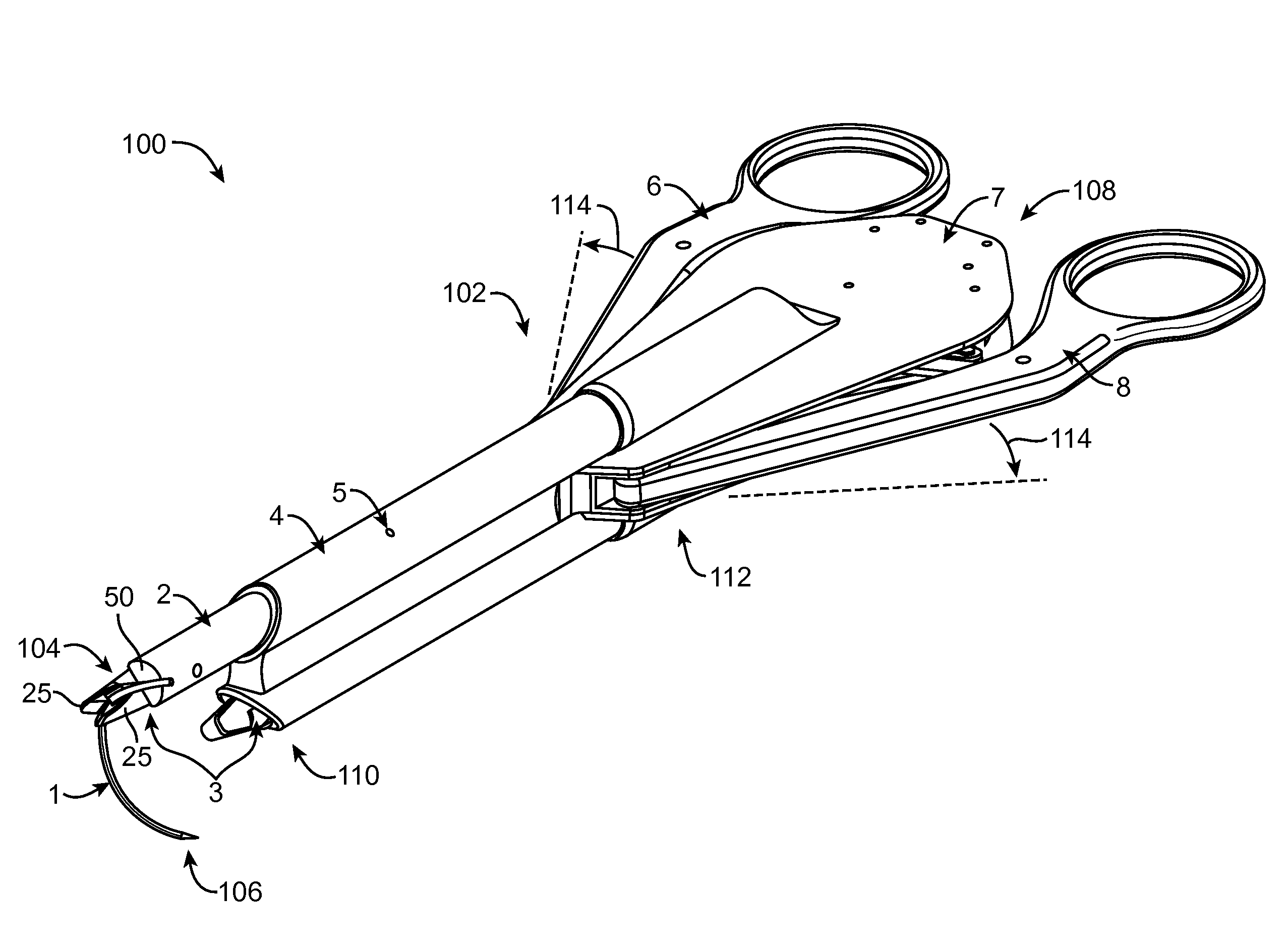
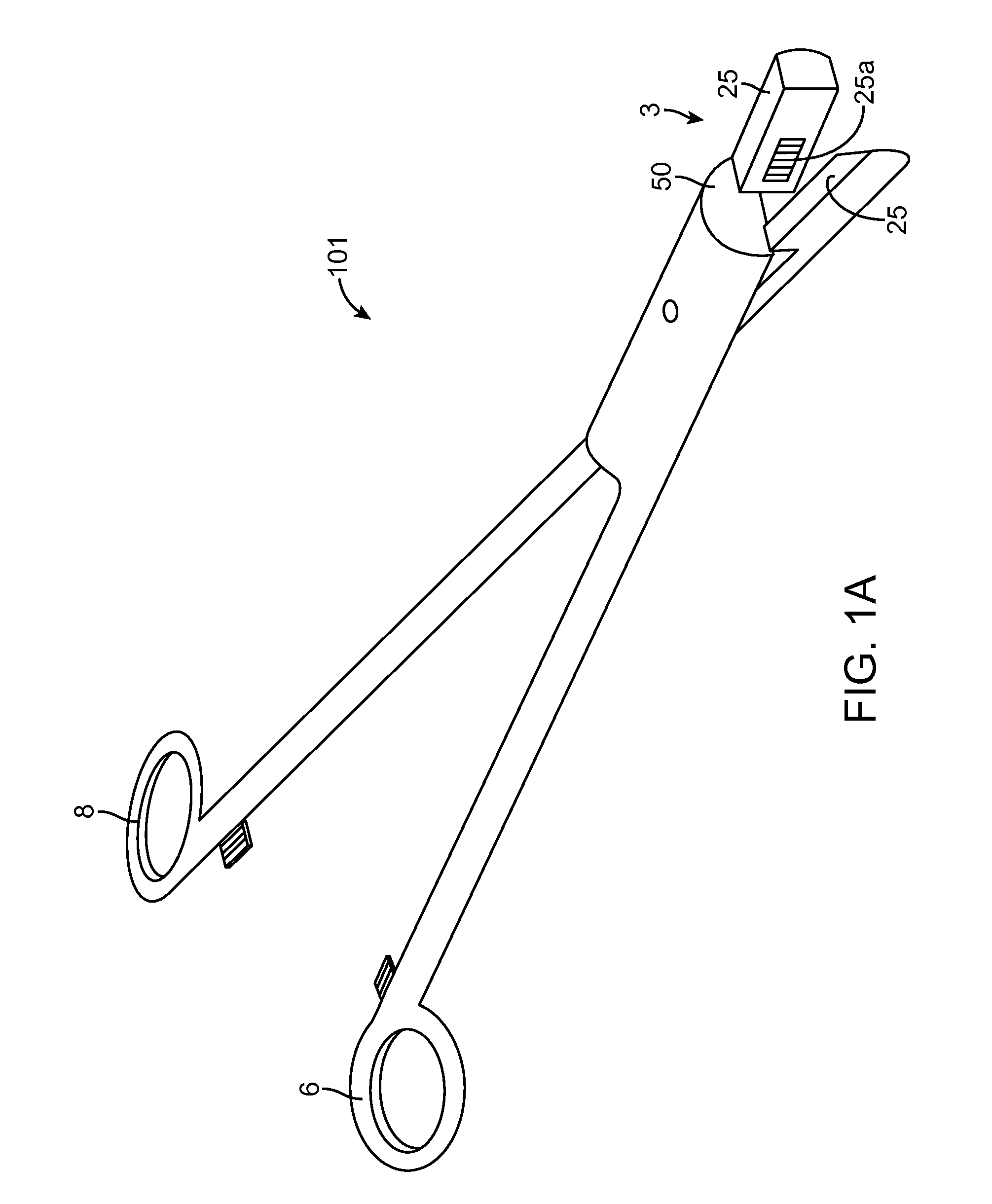
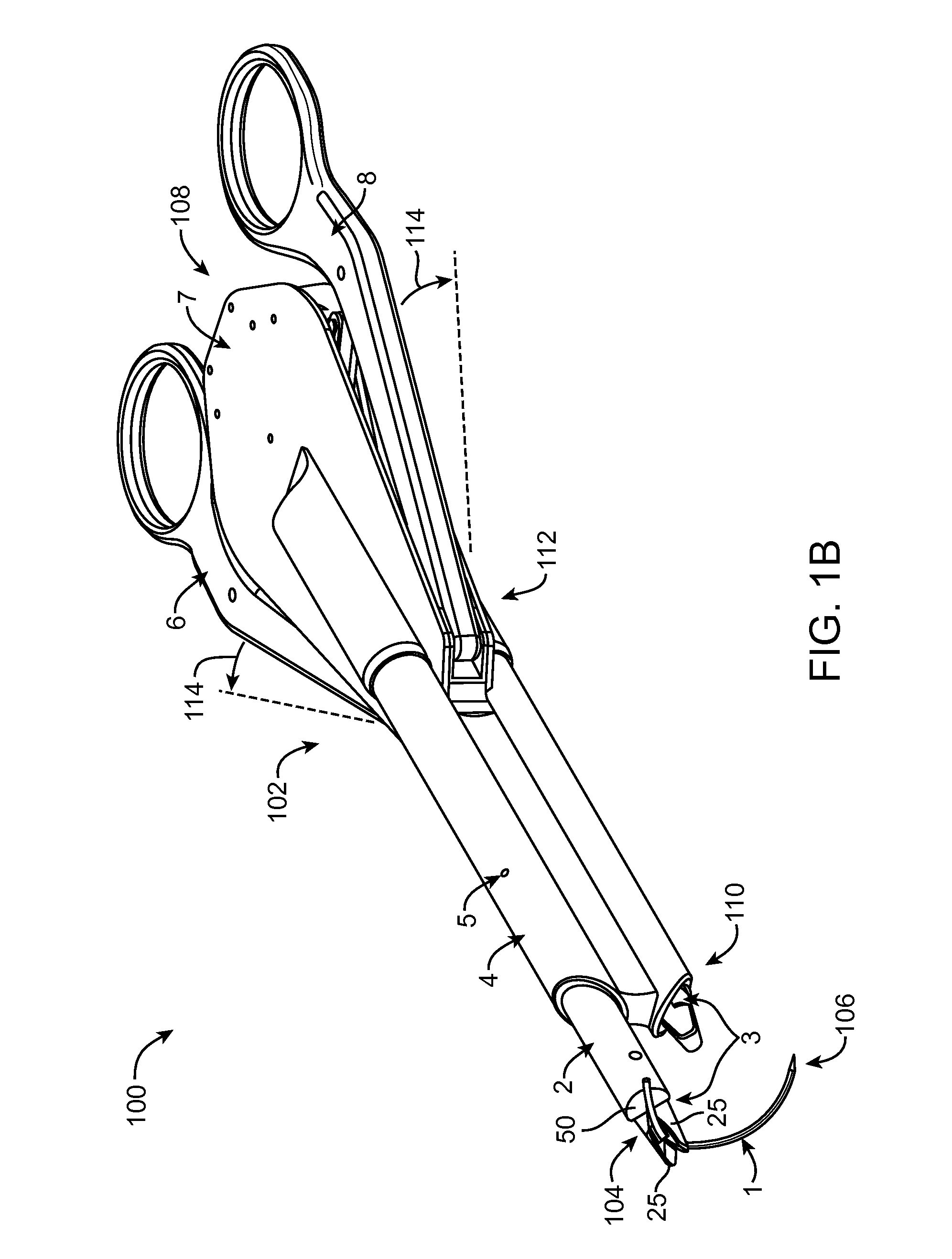
[0036]The present invention is generally directed to improved medical suturing devices, systems, and methods. Exemplary embodiments of the invention provide improved suturing devices and methods for suturing tissues that can significantly improve the positioning and alignment of a needle held in a suturing device, particularly useful when suturing of long incisions or where large numbers of stitches are to be deployed.

[0037]The invention should find a wide variety of applications for stitching anatomical tissues in both humans and animals. Along with endoscopic operations (for example, in laparoscopy) these structures and methods may find use in other areas of surgery where tissues are to be stitched, providing particular advantages for stitching of large incisions by increasing the ease and speed with which each individual stitch may be placed, as well as facilitating and expediting the formation of knots in the suture. The suturing devices and associated methods described herein m...


PUM


Abstract

Improved medical suturing devices, systems, and methods for maintaining a position and orientation of a suture needle at a fixed location relative to a suturing device. An exemplary device include a clamp having opposing grasping surfaces for grasping the needle at a first location, and a needle contacting surface for contacting the needle at a second location, the second location a distance axially away from the first location so as to inhibit unintended movement of the needle relative to the device, which may include rotation of the needle about the first location and rotation of the needle about its axis. In many embodiments, the device includes a first and second clamp and a mechanism for alternating grasping of the needle between the first and second clamp. The device may also be incorporated into a single-clamp needle grasping device.

Description

CROSS-REFERENCE TO RELATED APPLICATIONS[0001]The present application claims the benefit under 35 USC 119(e) of U.S. Provisional Application No. 61 / 494,785 filed Jun. 8, 2011, the full disclosure of which is incorporated herein by reference in its entirety for all purposes.[0002]This application is generally related to U.S. Pat. No. 7,588,583 issued on Sep. 15, 2009; U.S. patent application Ser. No. 11 / 532,032 filed Sep. 14, 2006; U.S. patent application Ser. No. 12 / 535,499 filed Aug. 4, 2009; U.S. patent application Ser. No. 12 / 049,552 filed on Mar. 17, 2008; U.S. patent application Ser. No. 12 / 049,545 filed on Mar. 17, 2008; U.S. patent application Ser. No. 12 / 687,349 filed on Jan. 14, 2010; and U.S. Patent Application 61 / 358,764 filed on Jun. 25, 2010, the full disclosures of which are incorporated herein by reference.BACKGROUND OF THE INVENTION[0003]The present invention generally relates to medical devices, systems, and methods. In specific embodiments, the invention provides de...

Claims


Application Information

Patent Timeline
IPC IPC(8): A61B17/04
CPCA61B17/062A61B2017/00477A61B2017/00473A61B2017/0023
Inventor BELMAN, YURIZATYURYUKIN, ALEXANDER BORISOVICHMOORE, PATRICIA A.
Owner BOSS INSTR
Why Eureka
Try Eureka