Rivet machine

a rivet machine and feeding mechanism technology, applied in metal-working equipment, metal-working equipment, manufacturing tools, etc., can solve the problems of premature fatigue of springs, disadvantageous push of rivets, and jamming of feeding mechanisms

Active Publication Date: 2012-12-20
BTM COMPANY
View PDF5 Cites 25 Cited by
  • Summary
  • Abstract
  • Description
  • Claims
  • Application Information

AI Technical Summary

Benefits of technology

[0004]In accordance with the present invention, a fastener machine is provided. In another aspect, a rivet machine employs a rivet feeding mechanism. A further aspect includes a guide located at an intersection between a feed track and a feed rail with the guide having an angular offset orientation relative to both in order to deter ricocheting of the rivet back into the feed track when the rivet enters the feed rail. Moreover, an aspect of the present machine employs a rocker arm pivotable adjacent a feed rail with a finger of the rocker arm being moveable through a hole in a channel to selectively limit movement of the rivet in the channel. In another aspect, a biased plunger has: a longitudinally longer aspect ratio relative to its nominal width to deter misalignment or cocking during movement of the plunger, a stop surface abutting a flange of the plunger to deter fatigue of a biasing member, and / or a beveled hole edge to deter tripping of the rivet when the rivet moves past the hole. Yet another aspect of the rivet machine provides at least a return sensor, an advancing sensor, a rivet feed sensor and a controller. A method of using a rivet machine is additionally provided.

Problems solved by technology

This causes a pneumatically driven rivet to undesirably bounce back or ricochet off of the abutting wall of the feed rail (e.g., the top of the T) thereby either jamming the feeding mechanism or being out of position for the subsequent advancement of a pusher shaft.
The quick advancing movement of the rivet past each plunger causes each plunger to downwardly move at about 30 feet per second which prematurely fatigues the spring after a number of cycles.
Moreover, the air pressure can disadvantageously push the rivet past the plunger in the feed rail prior to advancement of the pusher shaft.

Method used


Image

  • Rivet machine
  • Rivet machine
  • Rivet machine

Examples


Embodiment Construction

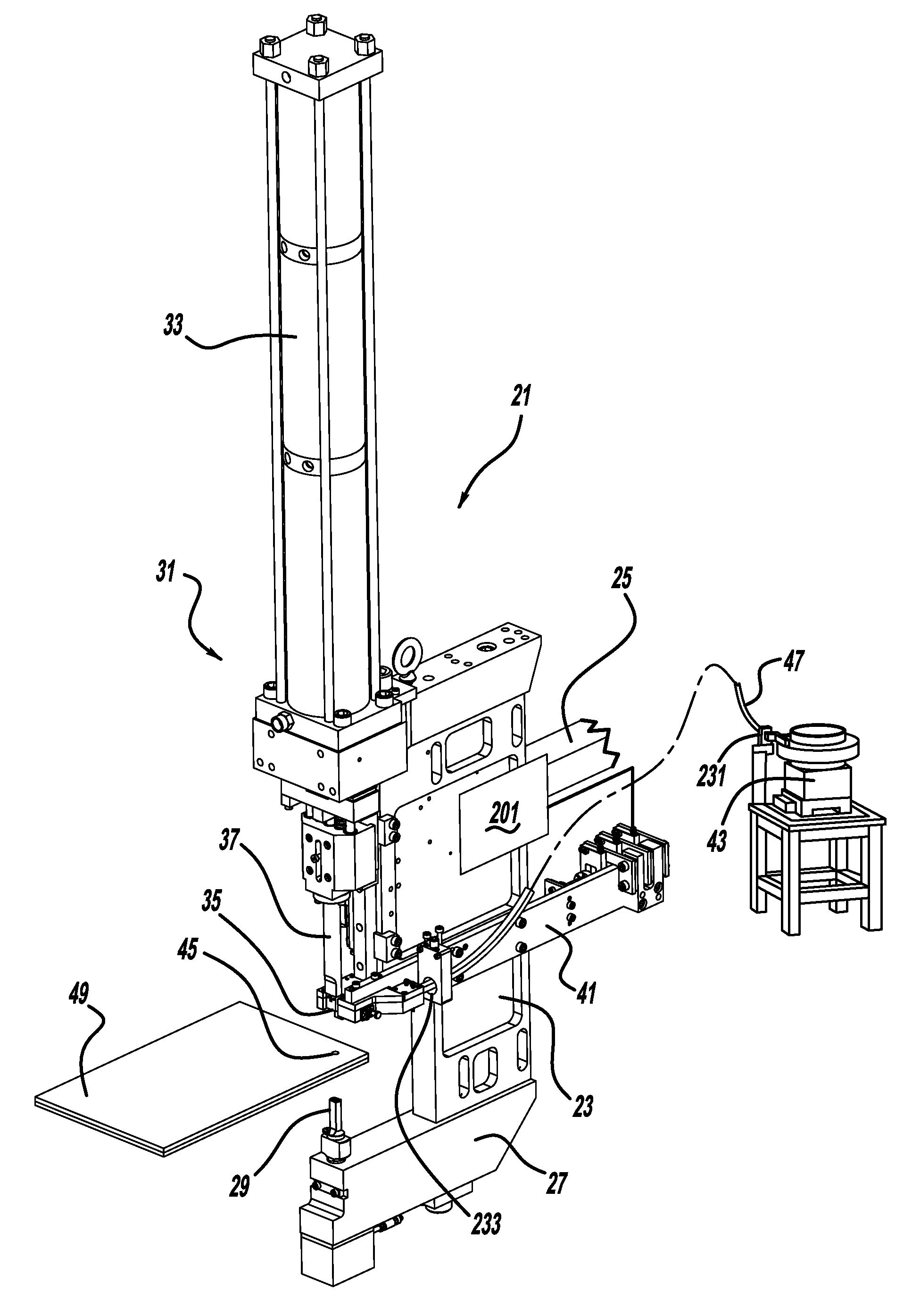
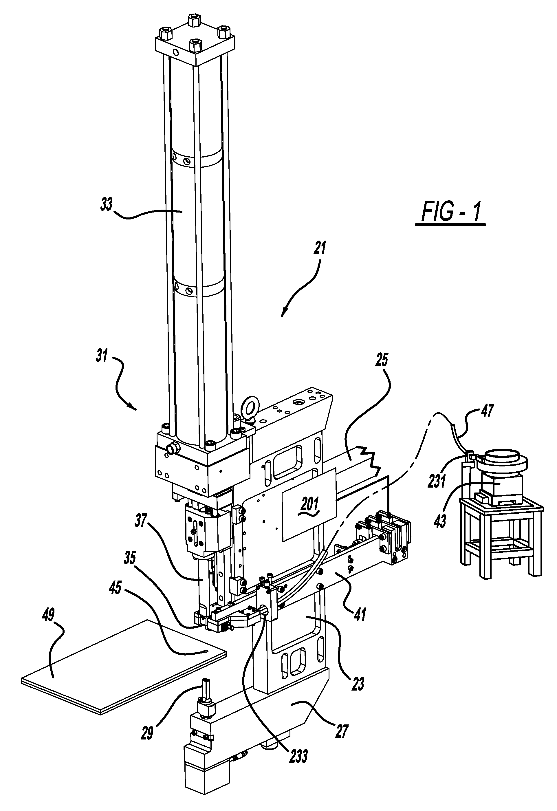
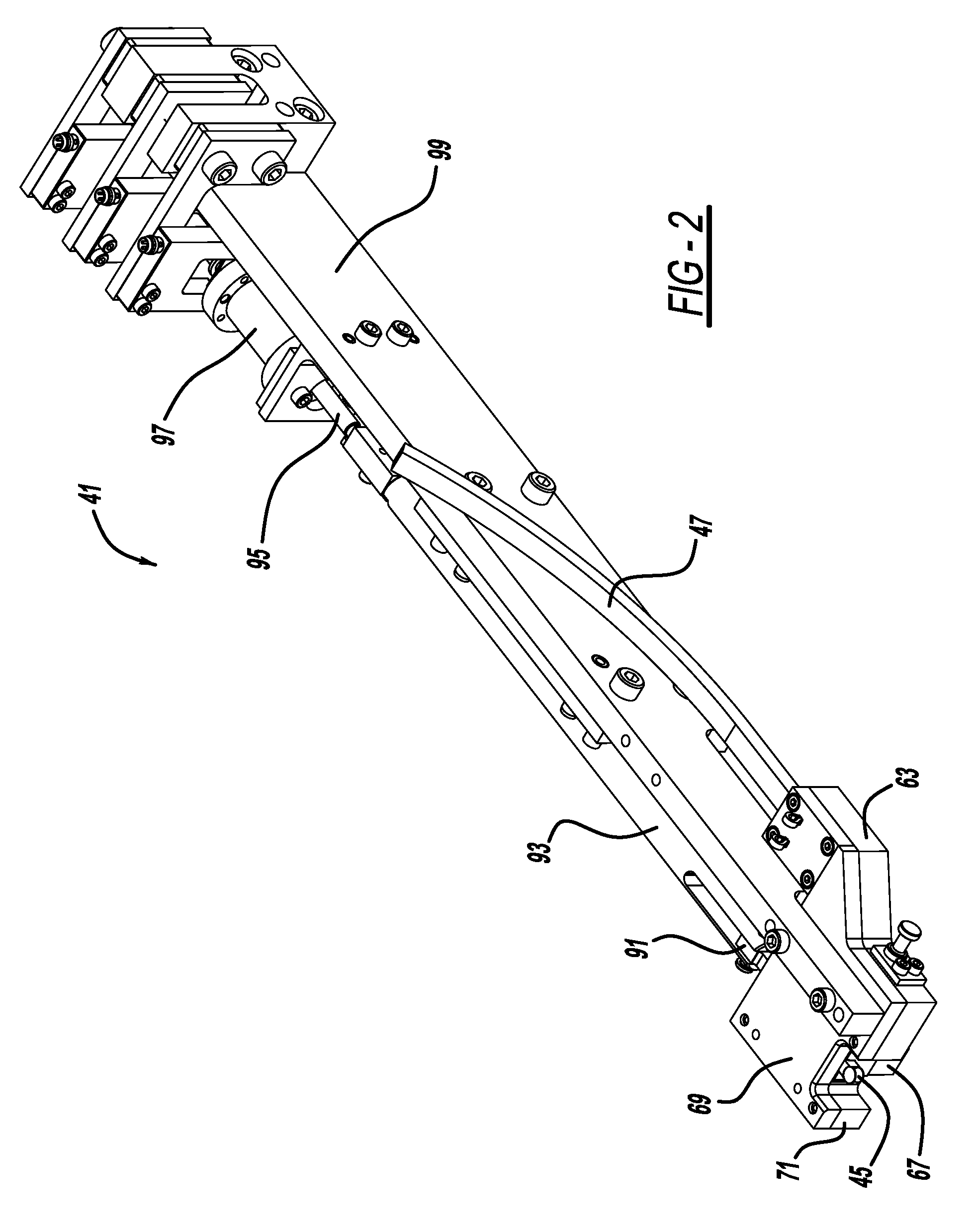
[0014]Referring to FIG. 1, a rivet setting machine 21 includes a C-frame 23 which is mounted to an articulated robotic arm 25 for automated movement between various operating positions within an industrial factory. An anvil section 27 of C-frame 23 has a die 29 mounted thereon. A ram assembly 31 is mounted to the opposite end of C-frame 23 and includes an air-over-oil fluid actuated cylinder 33, a nose piece 35 and a linearly moving ram 37. Alternately, cylinder 33 can be solely hydraulically, pneumatically, or less preferably, servo-motor actuated. A rivet feeding mechanism 41 is mounted to a generally middle segment of C-frame 23 and is elongated in a direction generally perpendicular to the movement direction of ram 37.

[0015]A vibratory bowl 43 supplies individualized fasteners, such as a self-piercing rivet 45, to feeding mechanism 41 via a pneumatically pressurized and flexible hose 47. When multiple workpiece sheets 49 are inserted between ram 37 and die 29, ram 37 will therea...


PUM

PropertyMeasurementUnit
angleaaaaaaaaaa
angleaaaaaaaaaa
angleaaaaaaaaaa

Abstract

A fastener machine is provided. In another aspect, a rivet machine employs a rivet feeding mechanism. A further aspect includes a guide located at an intersection between a feed track and a feed rail with the guide having an angular offset orientation relative to both in order to deter ricocheting of the rivet back into the feed track when the rivet enters the feed rail. Moreover, an aspect of the present machine employs a rocker arm.

Description

BACKGROUND AND SUMMARY[0001]This present invention relates generally to a fastener machine and more particularly to a feeding mechanism for a rivet machine.[0002]Various feeding and setting machines have been used for rivets. Such traditional machines are disclosed in U.S. Pat. Nos. 6,592,015 entitled “Feeding Heads for Fastening Machines” which issued to Gostylla et al. on Jul. 15, 2003, and U.S. Pat. No. 5,752,305 entitled “Self-Piercing Riveting Method and Apparatus” which issued to Cotterill et al. on May 19, 1998. Both of these patents are incorporated by reference herein.[0003]Another conventional, self-piercing rivet setting machine employs a right angled, T-shaped intersection between a guide track and feed rail paths. This causes a pneumatically driven rivet to undesirably bounce back or ricochet off of the abutting wall of the feed rail (e.g., the top of the T) thereby either jamming the feeding mechanism or being out of position for the subsequent advancement of a pusher ...

Claims


Application Information

Patent Timeline
Patent Type & Authority Applications(United States)
IPC IPC(8): B23P11/00
CPCB23P11/00B23P19/00B23P19/02B21J15/32Y10T29/53791Y10T29/53774Y10T29/53783Y10T29/53787Y10T29/53778Y10T29/5377
Inventor FAITEL, WILLIAM M.WEAVER, JR., ROBERT W.
Owner BTM COMPANY
Why Eureka
Try Eureka