Heat sink having juxtaposed heat pipes and method for manufacturing the same

a heat sink and heat pipe technology, applied in the field of heat sinks, can solve the problems of limited heat conductivity efficiency of the whole structure, damage or burnout of electronic heat-generating sources, and other heat pipes that cannot help inactive heat pipes to conduct heat, etc., and achieve the effect of increasing the thermal contact area and increasing the heat-dissipation efficiency of the heat sinks

Inactive Publication Date: 2012-12-20
COOLER MASTER DEVELOPMENT CORP
View PDF4 Cites 10 Cited by
  • Summary
  • Abstract
  • Description
  • Claims
  • Application Information

AI Technical Summary

Benefits of technology

[0007]The present invention is to provide a heat sink having juxtaposed heat pipes and a method for manufacturing the same. The respective heat pipes are juxtaposed and adhered to each other, thereby increasing the thermal contact area between the respective heat pipes and an electronic heat-generating source. By this arrangement, the heat-dissipating efficiency of the heat sink is increased greatly.

Problems solved by technology

However, it is an important issue to combine heat pipes with a heat-conducting base to generate a better heat-conducting or heat-dissipating effect.
However, since the heat-conducting coefficient of the dividing strip is much smaller that that of the heat pipe, the resultant heat-conducting efficiency of the whole structure is limited.
On the other hand, since the heat pipes are separated from each other by the dividing strips, if one heat pipe is inactive, the other heat pipes cannot help the inactive heat pipe to conduct the heat.
As a result, the electronic heat-generating source may suffer damage or burn down.

Method used


Image

  • Heat sink having juxtaposed heat pipes and method for manufacturing the same
  • Heat sink having juxtaposed heat pipes and method for manufacturing the same
  • Heat sink having juxtaposed heat pipes and method for manufacturing the same

Examples


Embodiment Construction

[0025]The detailed description and technical contents of the present invention will become apparent with the following detailed description accompanied with related drawings. It is noteworthy to point out that the drawings is provided for the illustration purpose only, but not intended for limiting the scope of the present invention.

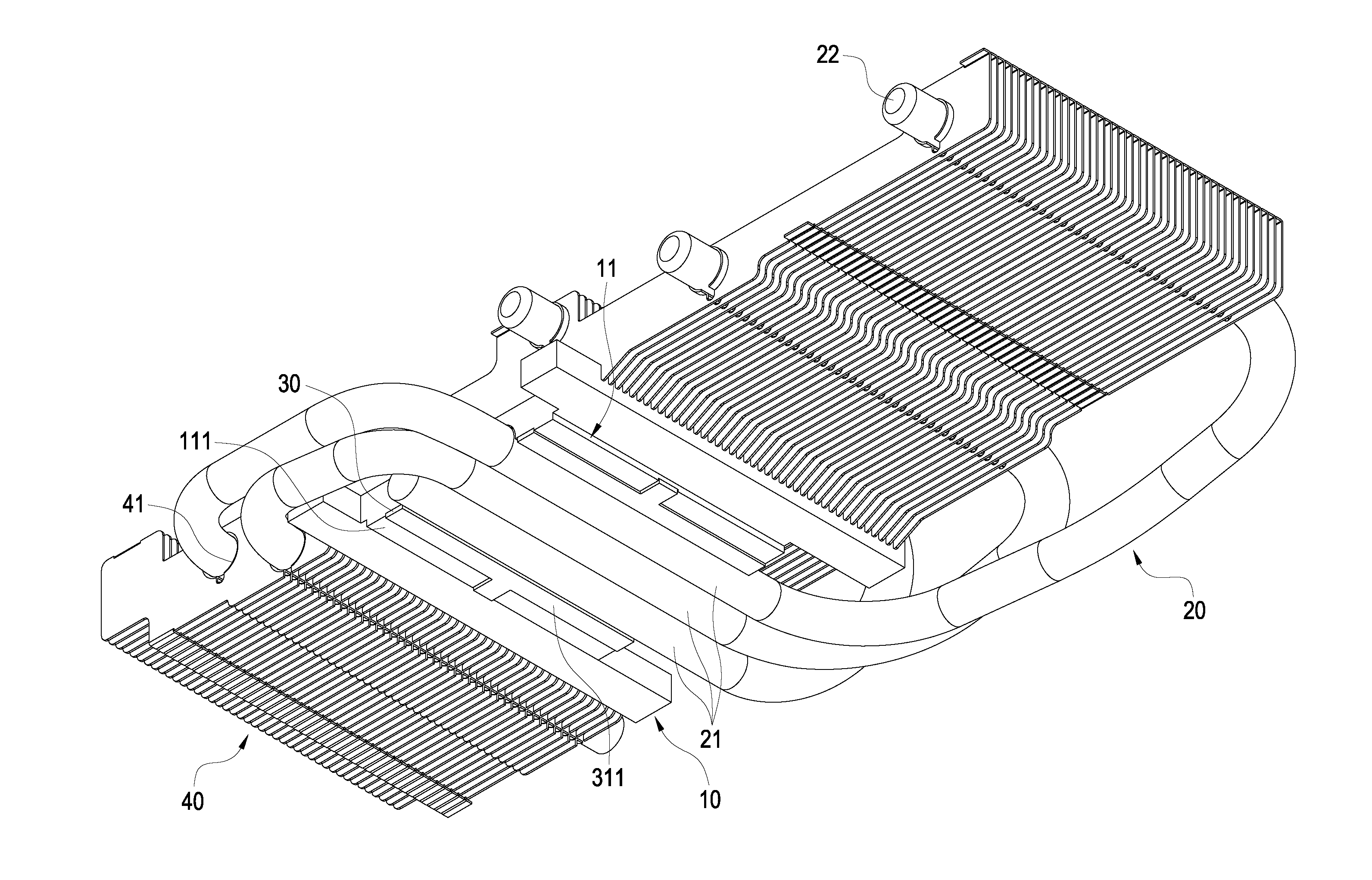
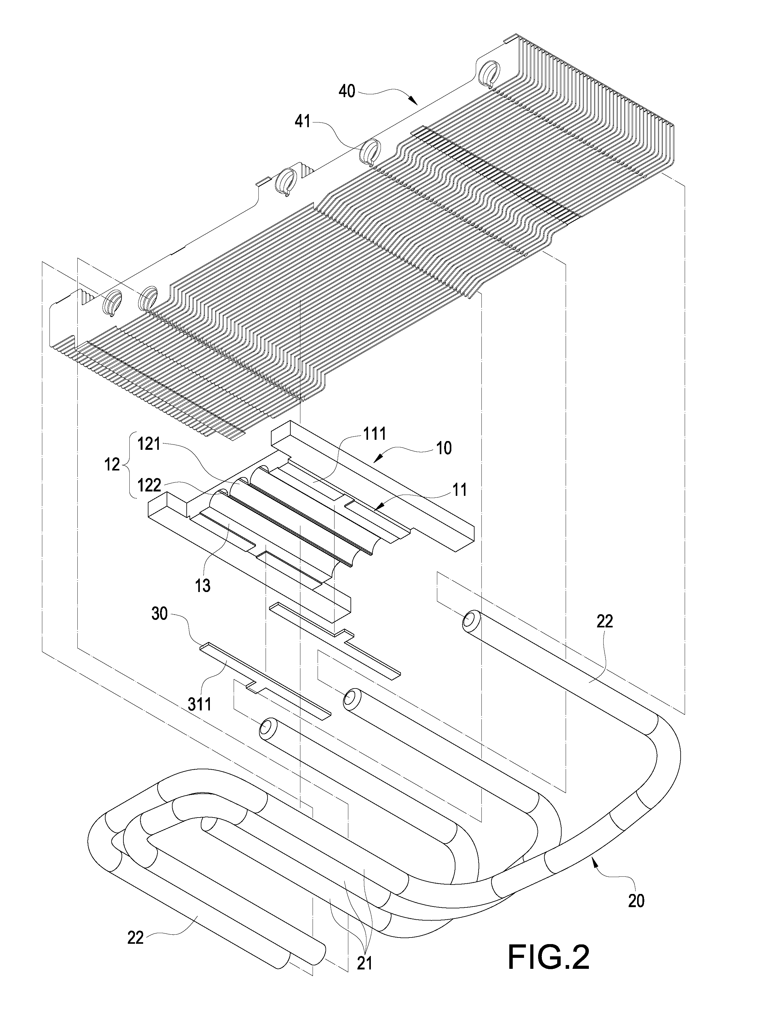
[0026]Please refer to FIGS. 2 and 4. The present invention provides a heat sink having juxtaposed heat pipes, which includes a base 10, a plurality of heat pipes 20, and a pair of side strips 30.

[0027]The base 10 is made of metallic materials such as aluminum or alloys thereof. In the present embodiment, the base 10 is formed into an H-shaped plate. The shape of the base 10 is not limited thereto, and may be formed into other shapes. The middle portion of the base 10 is provided with a protruding stage 11. The protruding stage 11 has a surface 111. The surface 111 is provided with an open trough 12. The interior of the open trough 12 is formed with three...


PUM

PropertyMeasurementUnit
heightaaaaaaaaaa
heat-conducting coefficientaaaaaaaaaa
heat-conductingaaaaaaaaaa

Abstract

The present invention relates to a heat sink having juxtaposed heat pipes and a method for manufacturing the same. The heat sink includes a base, a plurality of heat pipes and a pair of side strips. The base has a surface on which an open trough and an insertion trough on both sides of the open trough are provided. Each heat pipe has an evaporating section. The evaporating sections are juxtaposed in the open trough and adhered to each other. Each evaporating section has a planar surface. The side strips are fixed into the insertion troughs and protrude from the surface of the base. The planar surface of each evaporating section and the outer surface of each side strip are coplanar. By this structure, the thermal contact surface between the heat pipes and electronic heat-generating sources is increased, so that the heat-dissipating efficiency of the heat sink is improved.

Description

BACKGROUND OF THE INVENTION[0001]1. Field of the Invention[0002]The present invention relates to a heat sink, and in particular to a heat sink having juxtaposed heat pipes and a method for manufacturing the same.[0003]2. Description of Prior Art[0004]A heat-conducting module constituted by combining heat pipes with a heat-conducting base, or a heat sink constituted by combining heat-dissipating fins and heat pipes can conduct or dissipate the increasing heat generated by current processors. Thus, such a heat-conducting module or heat sink has replaced the conventional heat-dissipating structure constituted by merely heat-dissipating pieces. However, it is an important issue to combine heat pipes with a heat-conducting base to generate a better heat-conducting or heat-dissipating effect.[0005]The conventional heat-dissipating module includes a heat-conducting block and a plurality of heat pipes. The heat-conducting block is provided with a plurality of grooves parallel to one another...

Claims


Application Information

Patent Timeline
Patent Type & Authority Applications(United States)
IPC IPC(8): F28D15/04B21D53/02
CPCF28D15/0233F28D15/0275F28F1/32Y10T29/4935F28F2275/122F28F2275/04F28D2021/0028
Inventor LIN, CHUN-HUNGSHIEH, TUNG-YANGCHIU, YEN-HSIANGLEE, CHUN-YI
Owner COOLER MASTER DEVELOPMENT CORP
Why Eureka
Try Eureka