Shielding protection cover for FLIR (Forward Looking Infra-Red) thermal imager

An infrared thermal imaging camera and shielding protection technology, which is applied in the direction of instruments, scientific instruments, measuring devices, etc., can solve the problems of affecting the efficiency of heat dissipation, large surface temperature changes, and low exhaust efficiency of exhaust outlets, so as to avoid temperature changes Excessively large, the effect of increasing the heat dissipation contact area

Active Publication Date: 2018-04-10
重庆普永科技发展有限公司
View PDF3 Cites 5 Cited by
  • Summary
  • Abstract
  • Description
  • Claims
  • Application Information

AI Technical Summary

Problems solved by technology

[0005] The purpose of the present invention is to provide a FLIR infrared thermal imaging camera shielding cover to solve the problem of directly passing through the air inlet pipe to dissipate heat from the internal infrared thermal imaging instrument components in the above background technology, resulting in a small heat dissipation surface and directly Contacting the air volume to the surface of the infrared thermal imaging instrument will cause the surface temperature to change too much, causing damage to the equipment. At the same time, when the internal heat is large, the air exhaust efficiency of the exhaust port is low, resulting in the formation of hot air circulation inside, which affects the heat dissipation. efficiency problem

Method used


Image

  • Shielding protection cover for FLIR (Forward Looking Infra-Red) thermal imager
  • Shielding protection cover for FLIR (Forward Looking Infra-Red) thermal imager
  • Shielding protection cover for FLIR (Forward Looking Infra-Red) thermal imager

Examples


Embodiment Construction

[0022] The following will clearly and completely describe the technical solutions in the embodiments of the present invention with reference to the accompanying drawings in the embodiments of the present invention. Obviously, the described embodiments are only some, not all, embodiments of the present invention. Based on the embodiments of the present invention, all other embodiments obtained by persons of ordinary skill in the art without making creative efforts belong to the protection scope of the present invention.

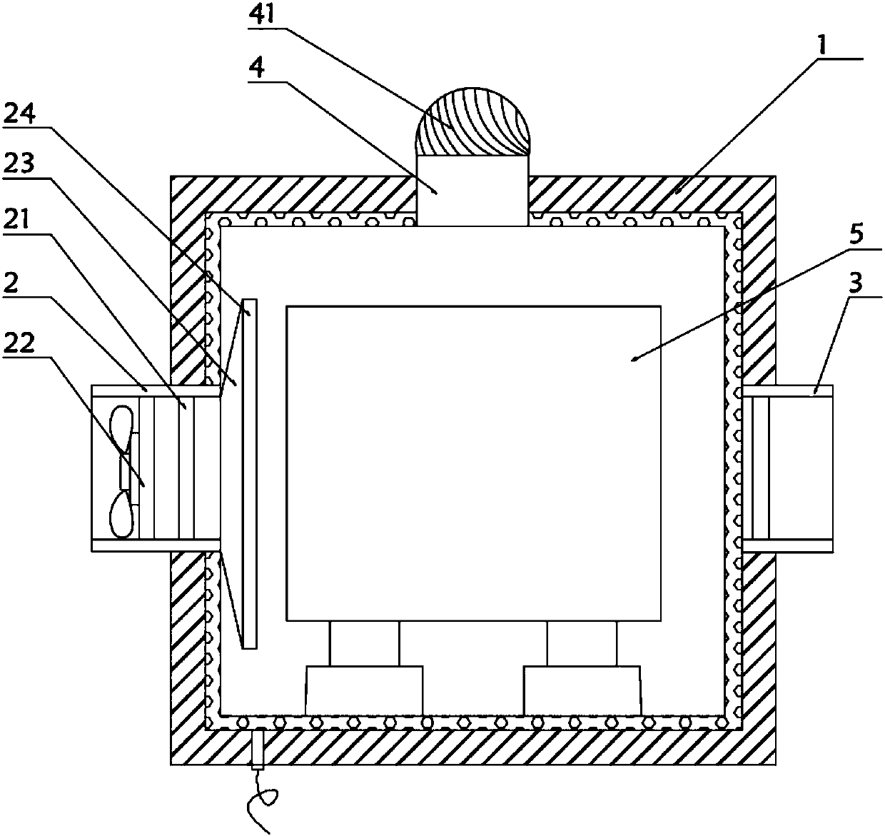
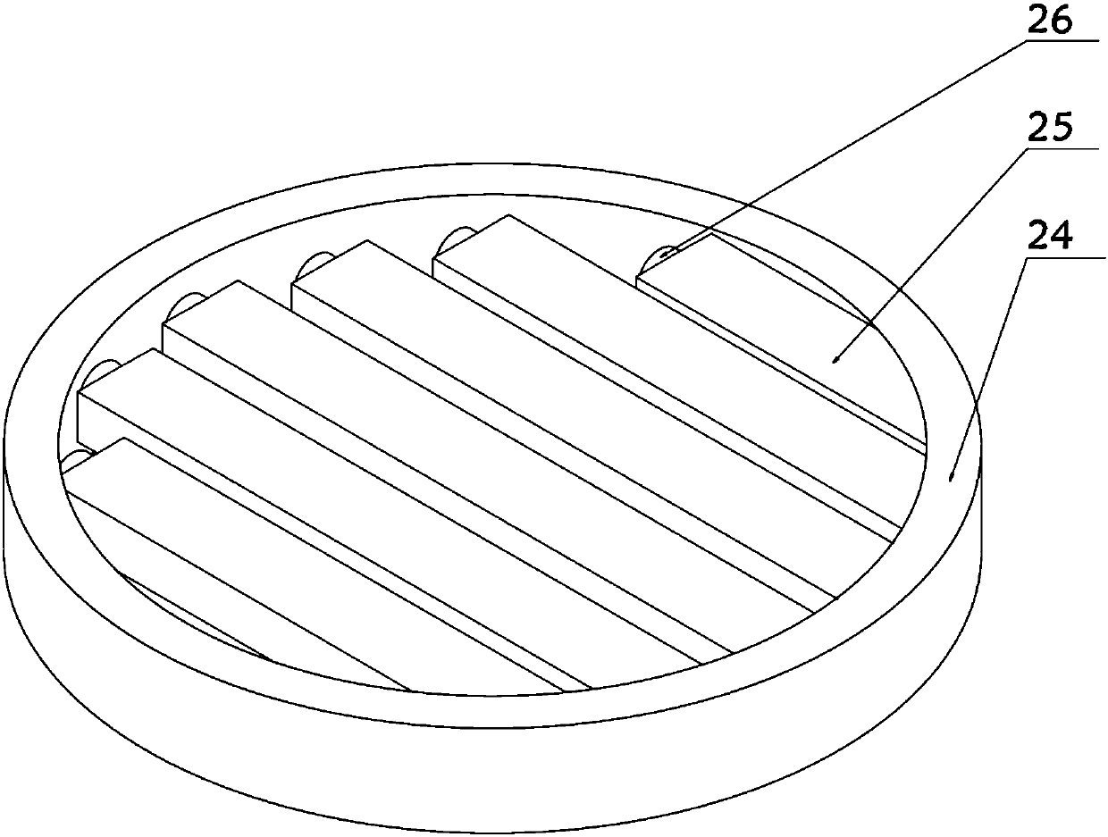
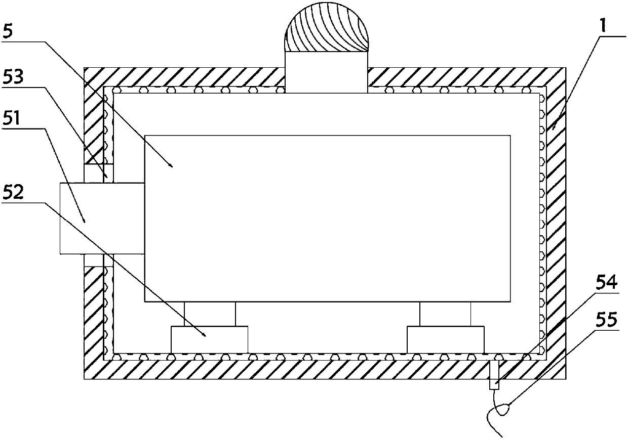
[0023] see Figure 1-3 , the present invention provides a technical solution:

[0024] A shielding cover for a FLIR thermal imaging camera, such as figure 1 and figure 2 As shown, it includes a protective shell 1, one side of the protective shell 1 is provided with an air inlet channel 2, the other side of the protective shell 1 is provided with an air outlet channel 3, and the top of the protective shell 1 is provided with an exhaust channel 4, and the pro...


PUM


Abstract

The invention relates to the technical field of FLIR (Forward Looking Infra-Red) thermal imagers, especially a shielding protection cover for an FLIR thermal imager. The cover comprises a protection housing, wherein side of the protection housing is provided with an air incoming channel, and the other side of the protection housing is provided with an air outgoing channel. The top of the protection housing is provided with an air exhaust channel. Air can move along the inner wall of a diffusion tube, and is exhausted from one end with the bigger diameter of the diffusion tube shaped like a circular truncated cone. Meanwhile, the end with the bigger diameter of the diffusion tube shaped like the circular truncated cone is greater than the height of the FLIR thermal imager, can achieve the heat dissipation of the whole FLIR thermal imager, and facilitates the increase of the heat dissipation contact area. When an air blowing disc makes contact with air, grids rotate with a rotating shaft, and air is exhausted from a gap between the two grids, thereby facilitating the dividing of air, and preventing the excessive temperature change of the FLIR thermal imager from causing the damages to the housing. A wind ball rotates to exhaust the hot air flow from the inside of the protection housing, thereby preventing the circulation of the hot air in the protection housing from causing impact on the heat dissipation efficiency.

Description

technical field [0001] The invention relates to the technical field of FLIR thermal imaging cameras, in particular to a shielding protective cover for FLIR thermal imaging cameras. Background technique [0002] Infrared thermal imaging camera is a non-contact testing instrument used to test the temperature distribution on the surface of the target to be tested. It detects high temperature resolution, clear infrared images, and diversified temperature displays. It can detect hot spots and hot spots more intuitively. The shape and distribution of points in the hot zone, as a precision instrument, has a sophisticated design, complex structure, and high cost. At the same time, it also has high requirements for the use environment, such as operating temperature, humidity, shock, vibration, and electronic equipment compatibility. etc. If the working temperature of the main body is too high, the infrared thermal imaging camera will not work normally, which will directly affect the ...

Claims


Application Information

Patent Timeline
Patent Type & Authority Applications(China)
IPC IPC(8): G01J5/04
CPCG01J5/048
Inventor 梅春燕
Owner 重庆普永科技发展有限公司
Why Eureka
Try Eureka