Heat radiation structure for electronic component

A technology of electronic components and heat dissipation structure, which is applied in the direction of electrical components, magnetic field/electric field shielding, cooling/ventilation/heating transformation, etc., can solve the problems of unsatisfactory heat dissipation, large weight, small contact area, etc., and achieve light weight and heat conduction The effect of large contact area and fast heat conduction

Inactive Publication Date: 2016-01-06
WUJIANG XINTA FORWARD HARDWARE FACTORY
View PDF6 Cites 4 Cited by
  • Summary
  • Abstract
  • Description
  • Claims
  • Application Information

AI Technical Summary

Problems solved by technology

However, copper is used as a heat dissipation material, although its heat dissipation speed is fast, but its weight is large, the contact area is small, and the heat dissipation is not ideal.

Method used


Image

  • Heat radiation structure for electronic component
  • Heat radiation structure for electronic component

Examples


Embodiment Construction

[0026] The present invention will be further described in detail below in conjunction with the accompanying drawings and specific preferred embodiments.

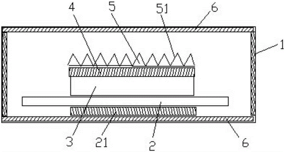
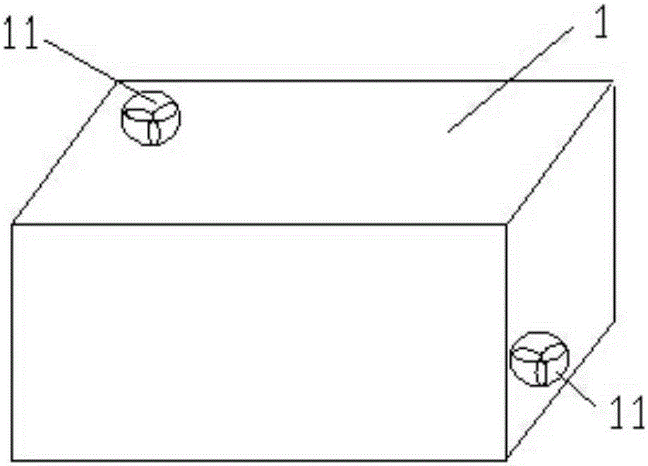
[0027] Such as figure 1 and figure 2 As shown, a heat dissipation structure for electronic components includes a shielding case 1 , two silent fans 11 , a thermally conductive adhesive layer 4 and a thermally conductive metal sheet 5 .

[0028] The shielding shell is built with a PCB board, and the PCB board is provided with electronic components.

[0029] The two silent fans are arranged at a diagonal position on the top and side of the shielding shell, which can form air convection.

[0030] The top of the electronic components is provided with a heat-conducting adhesive layer, and the top of the heat-conducting adhesive layer is provided with a heat-conducting metal sheet; the heat-conducting metal sheet is provided with a heat-conducting groove, and the heat-conducting groove is mainly formed by arranging several meta...


PUM


Abstract

The invention discloses a heat radiation structure for an electronic component. The heat radiation structure comprises a shielding shell, two mute fans, a heat conduction rubber layer and a heat conduction metal sheet; a PCB plate is arranged in the shielding shell; the PCB plate is provided with the electronic component; one mute fan is arranged on the top of the shielding shell and the other mute fan is arranged in the position of a diagonal line of the side part of the shielding shell to form air convection; the heat conduction rubber layer is arranged on the top of the electronic component; the heat conduction metal sheet is arranged on the top of the heat conduction rubber layer; a heat conduction groove is formed in the heat conduction metal sheet; and the heat conduction groove is formed by a plurality of metal strips arranged in parallel. By adoption of the structure and due to the setting of the heat conduction groove in the conduction metal sheet, the heat conduction structure is light in weight, large in heat conduction contact area, and rapid in heat conduction; meanwhile, the two mute fans can take away the heat absorbed by the heat conduction metal sheet in the convection manner; and in addition, due to the setting of the shielding shell and the heat conduction rubber layer, the electronic components can be separated mutually in heat conduction without causing signal interference.

Description

technical field [0001] The invention relates to a heat dissipation device, in particular to a heat dissipation structure for electronic components. Background technique [0002] Since the invention of electronic components, they have been used more and more in modern industry and modern life. For modern industry, especially mining, chemical industry, electric power, industrial manufacturing and other fields. For example, the electronic components attached to the PCB will generate thermal effects while working, and the temperature will continue to rise. If the heat is not taken away in time, it will cause heat accumulation and temperature rise, and eventually burn out the electronic components themselves and other components on the PCB board, or may affect the normal operation of the PCB board. [0003] At present, the heat dissipation methods of electronic components mainly include: heat conduction, convection and radiation. Heat conduction refers to the transfer of heat f...

Claims


Application Information

Patent Timeline
Patent Type & Authority Applications(China)
IPC IPC(8): H05K7/20H05K9/00
Inventor 杨和荣
Owner WUJIANG XINTA FORWARD HARDWARE FACTORY
Why Eureka
Try Eureka