
Flexible-usage travel suite

a technology for travel suites and seating arrangements, applied in the direction of seating arrangements, aircraft crew accommodation, transportation and packaging, etc., can solve the problems of increased weight, expense and complexity, and inability to design the seating components in this fashion inherently requires design compromises,

Active Publication Date: 2012-12-20
BE AEROSPACE INCORPORATED
View PDF18 Cites 64 Cited by
  • Summary
  • Abstract
  • Description
  • Claims
  • Application Information

AI Technical Summary

Benefits of technology

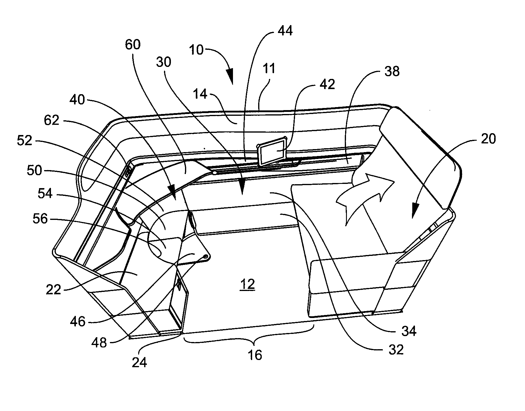
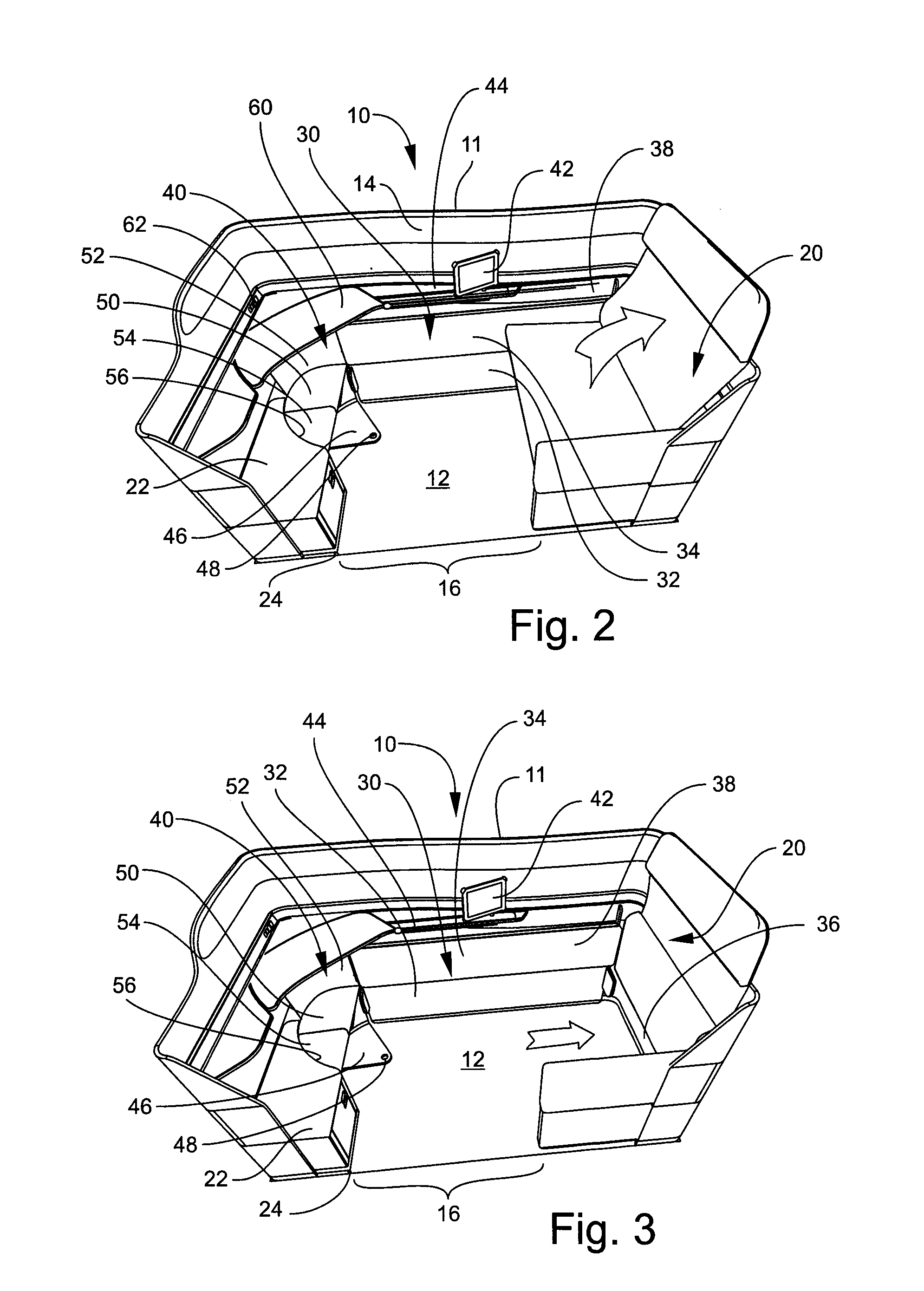
[0005]These and other objects and advantages of the invention are achieved by providing a flexible-usage travel suite that includes an enclosure having a floor, surrounding walls defining a predetermined area and an egress / ingress opening. A seat is positioned adjacent a first side of the enclosure and is moveable between a deployed seating configuration and a stowed storage configuration against the first side of the enclosure. A bed is positioned adjacent a second side of the enclosure and is moveable between a deployed lie-flat configuration when the seat is in its stowed storage configuration, and a stowed storage position when the seat is in its deployed seating configuration. A utility chair is positioned adjacent a third side of the enclosure opposite the first side of the enclosure and is moveable between a deployed use configuration when the bed is in its stowed storage configuration, and a stowed configuration when the bed is in its deployed lie-flat configuration. A utility table is positioned within the enclosure and is moveable among a stowed position, a first use position forward of the utility chair, and a second use position forward of the seat.

Problems solved by technology

Designing seating components in this fashion inherently requires design compromises.
For example, the requirement for a seat to have a back, bottom and leg rest that move relative to each other inherently requires numerous motors and linkage elements that cause increased weight, expense and complexity, as well as laterally-extending creases between the cushions that cause the bed surface to be not truly flat.
In addition, the g-loading requirements for seats require relatively hard foam cushioning that is uncomfortably hard when used as a bedding surface.

Method used


Image

  • Flexible-usage travel suite
  • Flexible-usage travel suite
  • Flexible-usage travel suite

Examples


Embodiment Construction

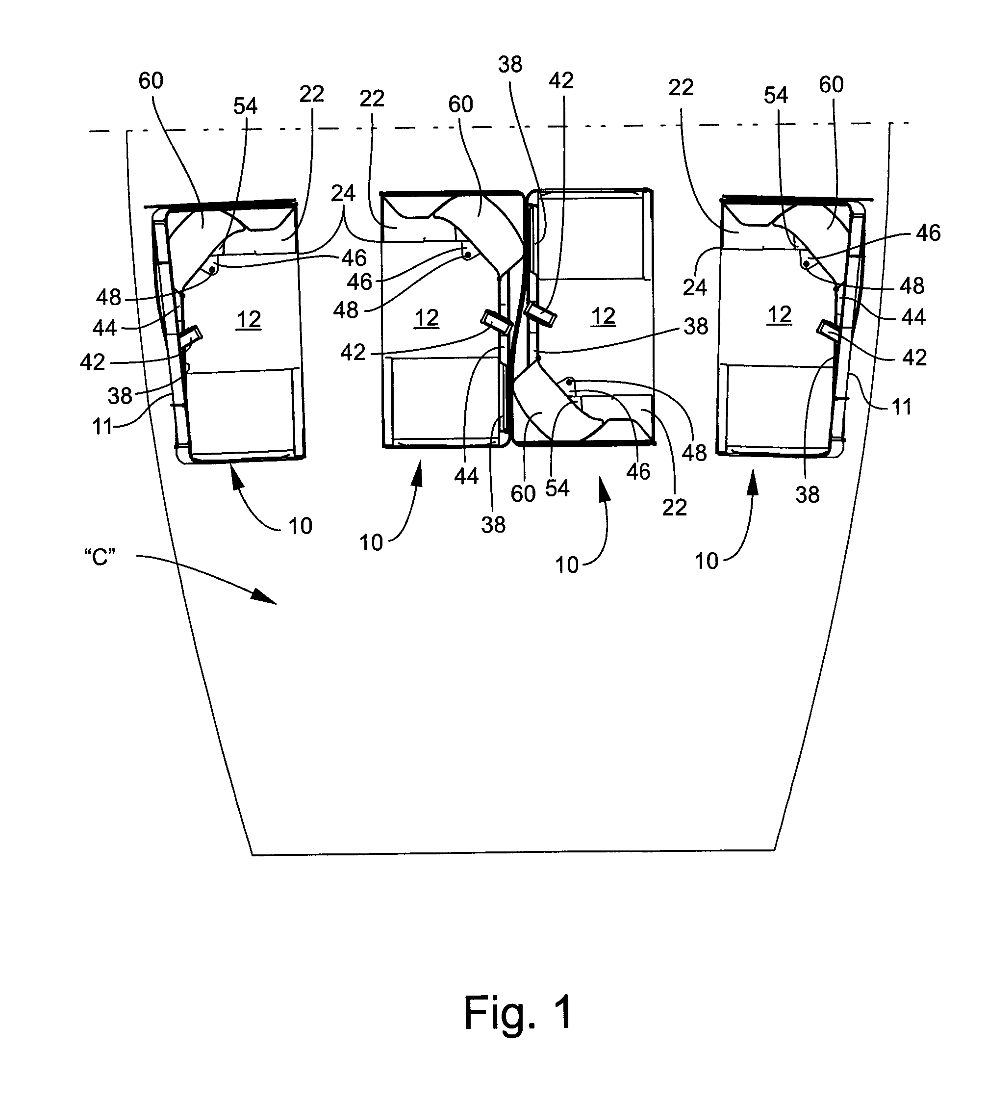
[0037]Referring now specifically to the drawings, a cabin floor plan showing placement of flexible-usage travel suites 10 in a premium class cabin according to one preferred embodiment of the present invention is illustrated generally in FIG. 1. The travel suites 10 are configured and placed according to the space allocation and weight and balance requirements of the particular aircraft in which the travel suites 10 are installed. The travel suites 10 may be stand-alone units or may be designed to share adjacent walls. In one preferred embodiment shown in FIG. 1, four travel suites 10 are shown arrayed in a side-by-side configuration across the width of a premium class aircraft cabin “C.” Other similar arrays may be placed in the cabin “C” depending on the size of the cabin “C” and the proportion of total cabin space dedicated to the premium cabin.

[0038]In the embodiment disclosed in this application, each travel suite 10 is defined by an enclosure 11 that includes a floor 12 with s...


PUM


Abstract

A flexible-usage travel suite that includes an enclosure having a floor, surrounding walls defining a predetermined area and an egress / ingress opening. A seat is positioned adjacent a first side of the enclosure and is moveable between a deployed seating configuration and a stowed storage configuration against the first side of the enclosure. A bed is positioned adjacent a second side of the enclosure and is moveable between a deployed lie-flat configuration when the seat is in its stowed storage configuration, and a stowed storage position when the seat is in its deployed seating configuration. A utility chair and utility table are positioned within the enclosure and are moveable among a stowed position and a use position.

Description

TECHNICAL FIELD AND BACKGROUND OF THE INVENTION[0001]This invention relates to a flexible-usage travel suite that has application in a wide range of environments. The invention is not limited to any particular mode of usage, but usage within aircraft, vessels, and land vehicles is the environment within which the invention is described. The invention is more particularly described by way of illustration as a travel suite appropriate for use in premium class, long haul, international air carriers.[0002]Long haul international air carriers typically provide three classes of service for passengers—coach class, which accommodates the large majority of passengers at a relatively low fare and with minimal amenities; business class, which accommodates a relatively smaller number of higher fare-paying passengers with more amenities; and premium class, which accommodates relatively few passengers at relatively high fares with luxurious amenities, including premium food and beverages, large a...

Claims


Application Information

Patent Timeline
Patent Type & Authority Applications(United States)
IPC IPC(8): B64D11/06A47B83/00
CPCB64D11/0604B64D11/06B64D11/0605
Inventor JOHNSON, GLENN A.PLANT, TOMMY G.
Owner BE AEROSPACE INCORPORATED
Learn More