Method of measuring contact failure and contact failure measuring device

a technology of contact failure and measuring device, which is applied in the direction of measuring device, magnetic measurement, instruments, etc., can solve the problems of easy failure of electronic control system, difficult or highly tedious and time-consuming to identify the location to be repaired, and customer's loss of confidence in electronic control system, etc., to achieve stable detection of transient response variation, easy installation, and easy operation.

Inactive Publication Date: 2012-12-20
HONDA MOTOR CO LTD
View PDF7 Cites 4 Cited by
  • Summary
  • Abstract
  • Description
  • Claims
  • Application Information

AI Technical Summary

Benefits of technology

[0021]According to the present invention, it is possible to determine whether or not there is a contact fault in the terminal fitting portion of the harness while the harness remains connected, in the same manner as when an abnormality occurs. More specifically, while a contact fault temporarily does not occur even though the terminal fitting portion is connected unstably, current may continue to flow through the terminal fitting portion before external forces are applied thereto. However, when external forces are applied to the terminal fitting portion, the contact fault may be reproduced in an unstably connected region thereof, which instantaneously prevents current from flowing. Also, when the terminal fitting portion is connected again, a transient response variation in the induced magnetic field around the harness including the terminal fitting portion may increase temporarily. According to the present invention, the magnitude of the transient response variation in the induced magnetic field around the harness when external forces are applied is detected and displayed as an indicator of whether or not a contact state of the terminal fitting portion is acceptable. Consequently, it is possible to determine whether or not there is a contact fault in the terminal fitting portion based on the displayed indicator, without requiring the terminal fitting portion to be separated, i.e., while the harness remains connected in the same state as when an abnormality occurs.
[0022]The phenomenon in which the transient response variation in the induced magnetic field becomes temporarily larger can be detected in a region around the harness, which is spaced slightly from the terminal fitting portion. Therefore, even in a space such as the engine compartment of a vehicle, for example, which is crammed full of wires and components, the user can choose a measurement location where the magnetic sensor can be installed with ease. Consequently, the measuring process can be performed easily.
[0023]In addition, it is possible to detect a transient response variation in the induced magnetic field while the detecting element of the magnetic sensor and the harness are secured in a relative positional relationship. Accordingly, the magnetic sensor can stably detect a transient response variation in the induced magnetic field even when external forces are applied to the terminal fitting portion.

Problems solved by technology

It often is difficult or is highly tedious and time-consuming to identify the location to be repaired.
The operator may make a wrong diagnosis and replace the harness coupler with a new one, without realizing that the fault is due to a harness coupler contact failure, and the operator is unable to leave proof of the fault, which indicates the location of the failure.
When a wrong diagnosis is made or if the electronic control system is repaired as described above, even though the contact failure may be removed by detaching and attaching the harness coupler again, the same electronic control system fault tends to occur again, since the repair was not essential.
If the electronic control system suffers the same fault again, then the customer is likely to lose confidence in the electronic control system.
In addition, the normal harness coupler may possibly be unfairly treated as a defective component, and thus the manufacturer will be unable to carry out accurate quality analysis on the harness coupler.
It is highly difficult to diagnose contact failures that tend to take place temporarily due to vibrations caused while the vehicle is in motion.

Method used


Image

  • Method of measuring contact failure and contact failure measuring device
  • Method of measuring contact failure and contact failure measuring device
  • Method of measuring contact failure and contact failure measuring device

Examples


first embodiment

A. First Embodiment

1. Configuration

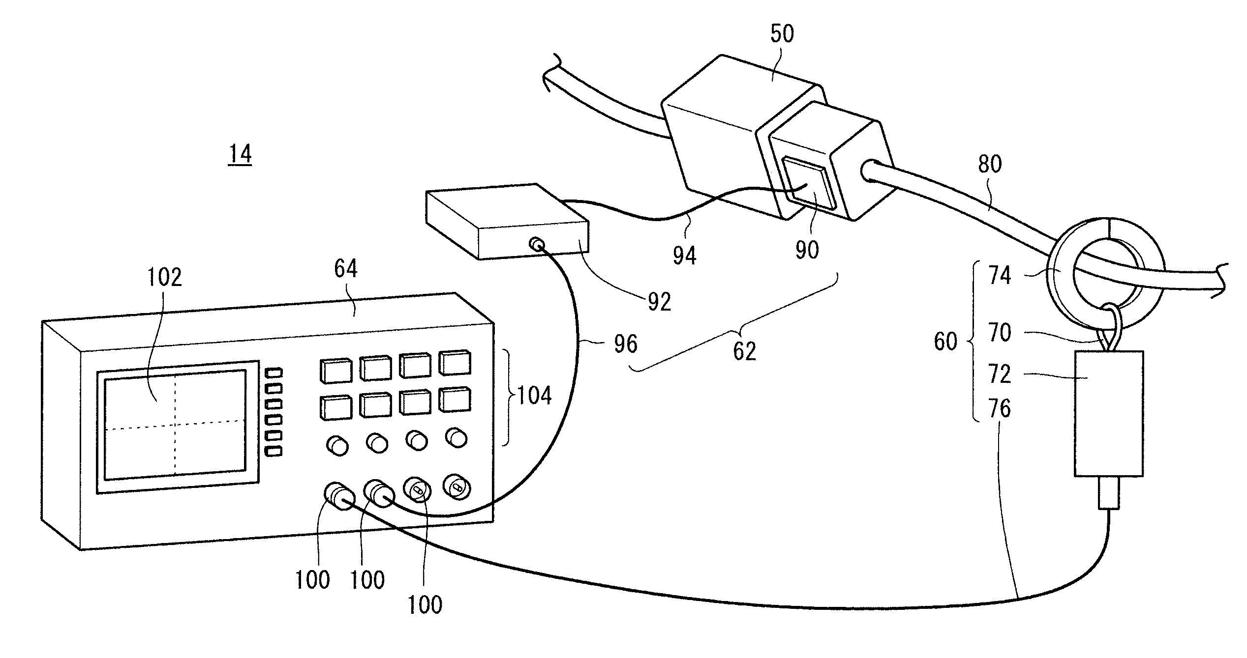
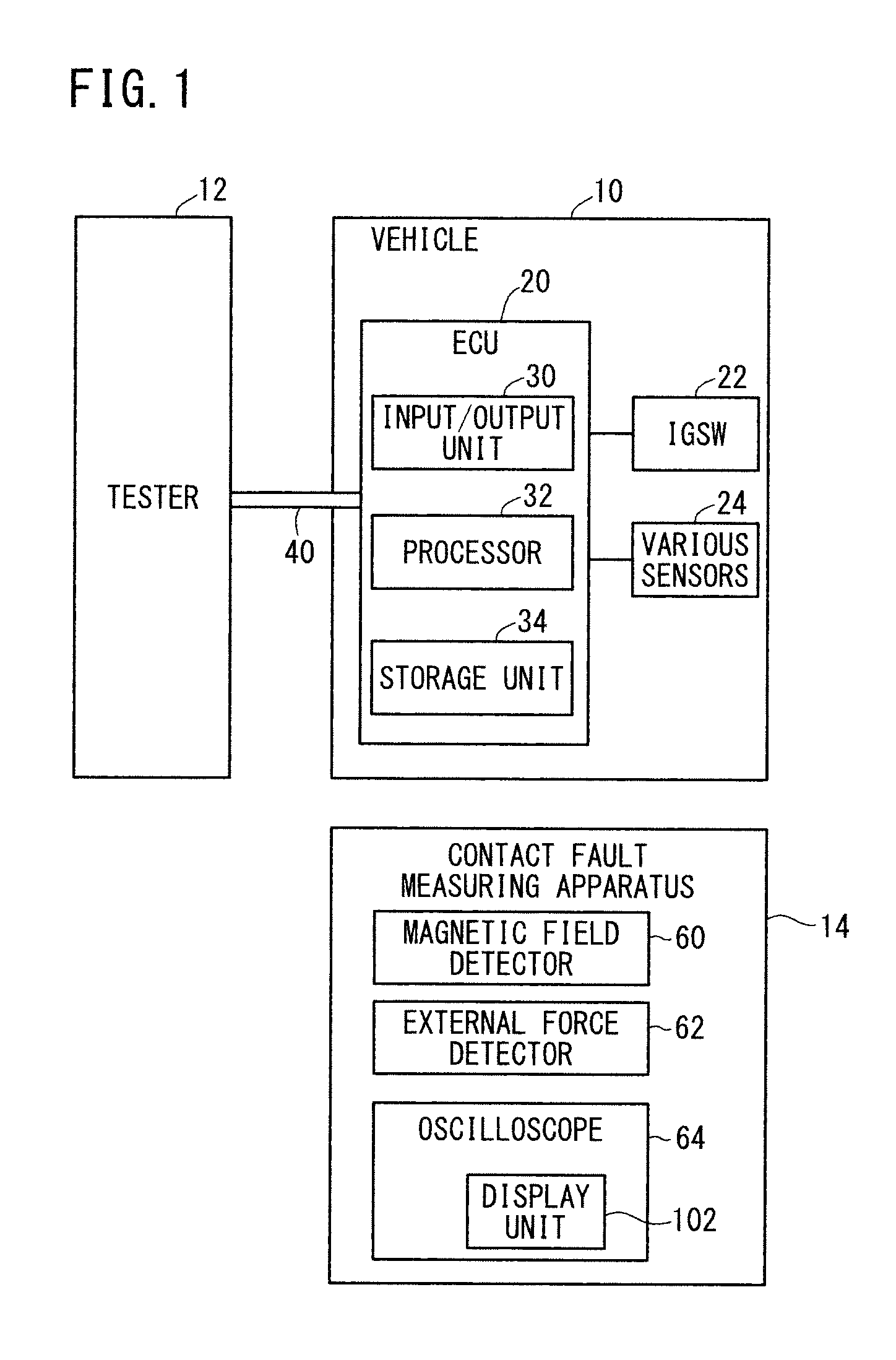
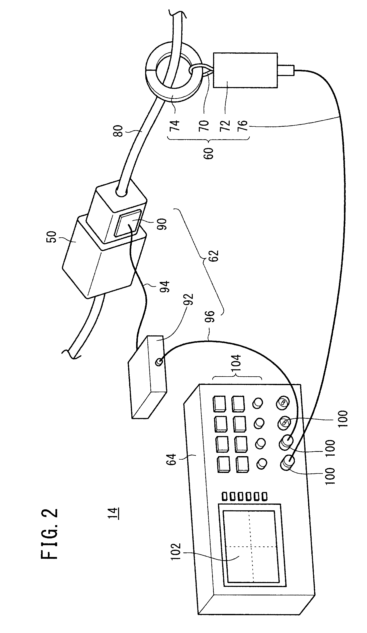
[0059](1) General Configuration of Contact Fault Measuring Apparatus 14 and Peripheral Regions Thereof

[0060]FIG. 1 is a block diagram showing a general configuration of a contact fault measuring apparatus 14 (hereinafter also referred to as a “measuring apparatus 14”) and peripheral regions thereof according to a first embodiment of the present invention. FIG. 1 shows, in addition to the measuring apparatus 14, a vehicle 10 to be measured together with a tester 12 for inspecting the vehicle 10. Although only one vehicle 10, one tester 12, and one measuring apparatus 14 are illustrated in FIG. 1, plural vehicles 10, plural testers 12, and plural measuring apparatus 14 may be employed.

[0061](2) Vehicle 10

[0062]The vehicle 10 has an electronic control unit 20 (hereinafter also referred to as an “ECU 20”), an ignition switch 22 (hereinafter also referred to as an “IGSW 22”) for turning on and off the ECU 20, and various sensors 24. The ECU 20 controls ...

second embodiment

B. Second Embodiment

1. Configuration

[0104]FIG. 11 is a view showing the manner in which a contact fault is measured using a contact fault measuring apparatus 14A (hereinafter also referred to as a “measuring apparatus 14A”) according to a second embodiment of the present invention. Parts of the second embodiment, which are identical to those of the first embodiment, will be denoted by identical reference characters, and such features will not be described in detail below.

[0105]The second embodiment differs from the first embodiment in that, whereas the user's finger is used to apply external forces to the coupler 50 according to the first embodiment (see FIG. 8), according to the second embodiment, a vibrating tool 120 is used to apply external forces to the coupler 50. Furthermore, whereas the acceleration sensor 90 is fixed to the coupler 50 according to the first embodiment (see FIG. 2), according to the second embodiment, the acceleration sensor 90 is fixed to the vibrating tool...

third embodiment

C. Third Embodiment

1. Configuration

[0109](1) Differences from the First Embodiment and the Second Embodiment

[0110]FIG. 12 is a view showing the manner in which a contact fault is measured using a contact fault measuring apparatus 14B (hereinafter also referred to as a “measuring apparatus 14B”) according to a third embodiment of the present invention. Parts of the third embodiment, which are identical to those of the first embodiment and the second embodiment, will be denoted by identical reference characters, and such features will not be described in detail below.

[0111]The third embodiment differs from the first embodiment and the second embodiment in that, whereas the user judges whether or not there is a contact fault based on the waveforms displayed on the display unit 102 according to the first embodiment and the second embodiment, according to the third embodiment, the measuring apparatus 14B itself determines whether or not a contact fault has occurred.

[0112]The measuring ap...


PUM


Abstract

In the disclosed method of measuring contact failure and contact failure measuring device, the magnitude of the excessive response fluctuation of the inductive magnetic field around a harness under measurement when an external force is applied to a terminal fitting part of the harness is detected by a magnetic sensor, and the result is displayed as an index of the quality of the contact state of the terminal fitting part.

Description

TECHNICAL FIELD[0001]The present invention relates to a contact fault measuring method (method of measuring contact failure) of and a contact fault measuring apparatus (contact failure measuring device) for measuring whether or not there is a contact fault in a terminal fitting portion of a harness in a wiring system.BACKGROUND ART[0002]There has heretofore been known a diagnosing apparatus for identifying the location of a fault in an electronic control system on a vehicle by reading a fault code that is recorded in an electronic control unit (ECU) incorporated in the vehicle. See, U.S. Pat. No. 5,491,631 (hereinafter referred to as “U.S. Pat. No. 5,491,631A”). According to U.S. Pat. No. 5,491,631A, in the event of a fault of a peripheral device connected to the ECU (1) of the vehicle, a self-diagnostic means (52) generates fault information and stores the generated fault information in a fault code storage means (53) (see, for example, column 13, lines 31-35). When the fault of a ...

Claims


Application Information

Patent Timeline
Patent Type & Authority Applications(United States)
IPC IPC(8): G08B21/00
CPCG01R31/006G01R31/04G01R33/02G01R33/0385G01R31/66
Inventor MARUYAMA, SUSUMUTSUCHIKIRI, HIDEYUKIFUKUDA, KOJIDEMACHI, ATSUSHI
Owner HONDA MOTOR CO LTD
Why Eureka
Try Eureka