Combined lighting, projection, and image capture without video feedback

Active Publication Date: 2012-12-20
MICROSOFT TECH LICENSING LLC
View PDF9 Cites 77 Cited by
  • Summary
  • Abstract
  • Description
  • Claims
  • Application Information

AI Technical Summary

Benefits of technology

[0010]More specifically, the Concurrent Projector-Camera dynamically synchronizes a combination of projector lighting on-state temporal compression in combination with on-state temporal shifting to open an intra-frame “capture time slot” for image capture during which no image is being projected. This capture time slot is created during the period in which a single image frame is being projected (hence the use of the term “intra-frame”), and represents a tradeoff between image capture time and decreased brightness of the projected image frame. Significantly, these capabilities are achieved without cancelling or eliminating entire projection frames, as is the case with various conventional techniques.
[0011]In other words, the Concurrent Projector-Camera dynamically controls an image projection device to create a capture time slot, during which no image is being projected. Therefore, this capture time slot allows images to be captured of the projection area without being corrupted by the projection. Further, the image capture enabled by the Concurrent Projector-Camera can be achieved at a frame rate at least as high as the frame rate of the projector, thereby enabling a wide variety of applications involving real-time multi-site video communications. Advantageously, all of these real-time multi-site video communications applications are achieved while completely eliminating any possibility of “visual echo” from any projection into any captured image that is then transmitted or broadcast to another location.
[0012]For example, in the case of LED-LCD based projectors, the Concurrent Projector-Camera creates the capture time slot by dynamically reducing or compressing the amount of time during which each LED is in an on-state during each image frame, as well as shifting those compressed LED on-state times within the time period for each image frame projection. This synchronized combination of LED on-state temporal compression and LED on-state temporal shifting opens a window of time (i.e., the aforementioned “c

Problems solved by technology

If two or more people are trying to share a common desktop where each has a camera and a projector, a video feedback loop will be created causing the video to become useless in a manner similar to audio feedback which results in high pitch squealing.
This problem is analogous to

Method used


Image

  • Combined lighting, projection, and image capture without video feedback
  • Combined lighting, projection, and image capture without video feedback
  • Combined lighting, projection, and image capture without video feedback

Examples


Example

[0023]In the following description of the embodiments of the claimed subject matter, reference is made to the accompanying drawings, which form a part hereof, and in which is shown by way of illustration specific embodiments in which the claimed subject matter may be practiced. It should be understood that other embodiments may be utilized and structural changes may be made without departing from the scope of the presently claimed subject matter.

[0024]1.0 Introduction:

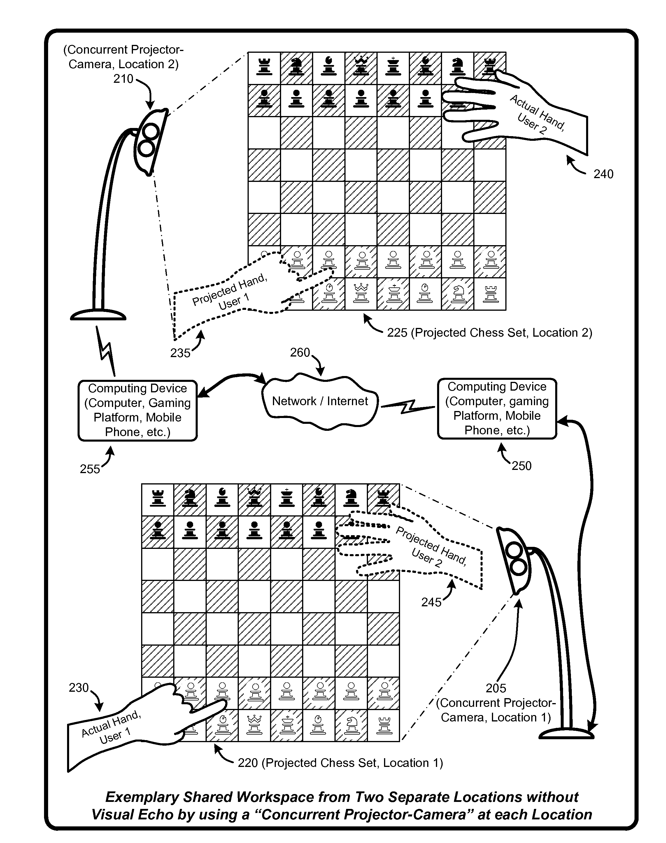
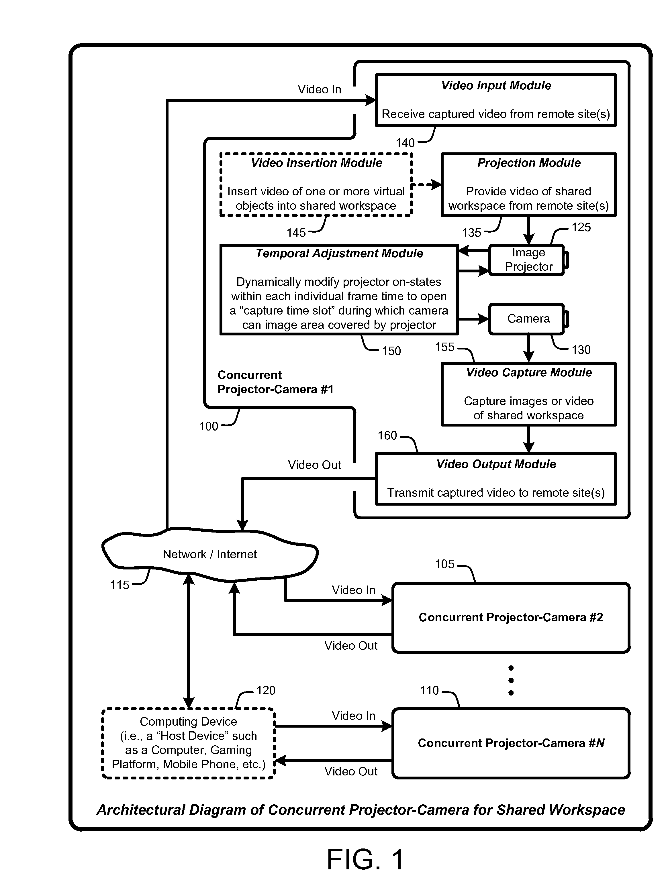
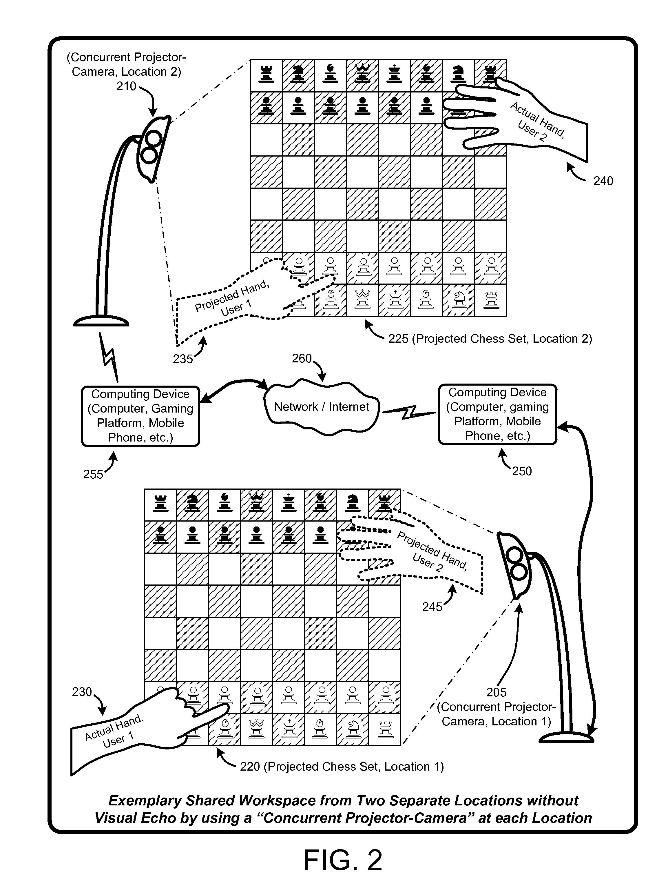
[0025]A “Concurrent Projector-Camera,” as described herein, uses an image projection device in combination with one or more cameras to enable various techniques that provide visually flicker-free projection of recorded or real-time images or video within a region or onto a surface, while real-time image or video capture is occurring in approximately that same space (which includes a sub-region of the projection area, the entire projection area or extended region encompassing the projection area). Note that rather than ...


PUM


Abstract

A “Concurrent Projector-Camera” uses an image projection device in combination with one or more cameras to enable various techniques that provide visually flicker-free projection of images or video, while real-time image or video capture is occurring in that same space. The Concurrent Projector-Camera provides this projection in a manner that eliminates video feedback into the real-time image or video capture. More specifically, the Concurrent Projector-Camera dynamically synchronizes a combination of projector lighting (or light-control points) on-state temporal compression in combination with on-state temporal shifting during each image frame projection to open a “capture time slot” for image capture during which no image is being projected. This capture time slot represents a tradeoff between image capture time and decreased brightness of the projected image. Examples of image projection devices include LED-LCD based projection devices, DLP-based projection devices using LED or laser illumination in combination with micromirror arrays, etc.

Description

BACKGROUND[0001]1. Technical Field[0002]A “Concurrent Projector-Camera” uses an image projection device in combination with one or more digital cameras and optional lighting to enable various techniques that provide visually flicker-free projection concurrently with real-time image or video capture in the same space in a manner that eliminates video feedback from the projection into the real-time image or video capture.[0003]2. Background Art[0004]If two or more people are trying to share a common desktop where each has a camera and a projector, a video feedback loop will be created causing the video to become useless in a manner similar to audio feedback which results in high pitch squealing. This problem has been referred to as “visual echo.”[0005]More specifically, “visual echo” represents the appearance of the projected contents viewed by a camera back into the projection over time. This problem is analogous to audio or acoustic echo in telephone communications where the person ...

Claims


Application Information

Patent Timeline
IPC IPC(8): H04N5/225H04N13/02
CPCG03B15/05H04N13/271H04N5/2256H04N5/247H04N5/33H04N9/3179H04N9/3194H04N7/141G06F3/00H04L12/1813G06F3/0425G06F3/0426G03B2215/05H04N13/207H04N13/254G03B17/54H04N23/56H04N23/90
Inventor JUNUZOVIC, SASABLANK, WILLIAM THOMASBATHICHE, STEVENGUPTA, ANOOPWILSON, ANDREW D.
Owner MICROSOFT TECH LICENSING LLC
Why Eureka
Try Eureka