
Method for designing and/or optimizing a surgical device

a surgical device and optimization technology, applied in the direction of osteosynthesis devices, internal osteosynthesis, instruments, etc., can solve the problems of increasing the x-ray dose of patients, significantly reducing the availability of pqct in hospitals, and increasing the dxa machine x-ray dose, so as to increase the purchase of implants and augment the physical properties of bone structure, the effect of minimal stress accumulation

Active Publication Date: 2012-12-20
AO TECH AG
View PDF7 Cites 107 Cited by
  • Summary
  • Abstract
  • Description
  • Claims
  • Application Information

AI Technical Summary

Benefits of technology

[0042]Additionally, the through hole in the implant should be easily accessible and should respect the local anatomy. For example, in the humerus the through hole can not start on the lateral bone surface, exit in the bicipital groove and enter again medially in the humerus. The boundary conditions given to the present algorithm will exclude those directions and find among the available directions those where the quality of the volumes is optimal. It is to be clarified that the algorithm leaves the chance to augment also in those areas where the implant has already good purchase, i.e. not only low quality for augmentation and high quality for better implant purchase.
[0049]An existing implant can be optimized with angular stable holes allowing precise local augmentation.
[0050]The direction of the anchoring parts of an existing implant can be optimized according to the high quality volumes characteristics of a given category, by maintaining the existing positions of the through holes.
[0054]In a further embodiment of said method said implant is a fixed angle implant. In fixed angle implants the directions of the anchoring parts are defined by the through holes. These are characterized by a mechanical locking method which allows consistently pre-drilling and inserting anchoring parts along the same through holes orientation.
[0061]In yet a further embodiment of said surgical device, in particular implant said through hole is designed as a variable angle hole for receiving a bone fixation element at a variable angle, said variable angle hole having a central axis corresponding to said optimal direction. This configuration allows the advantage that the variability of the angle allows the surgeon to align the bone fixation element upon insertion to take into account e.g. anatomical differences.

Problems solved by technology

At the same time this technique is more time consuming and increases the X-ray dose for the patient, making the pQCT availability in hospitals significantly lower than DXA machines.
In the clinical setting the space available to position an implant is substantially limited by the given surgical access.
Anatomically shaped implants limit even more the chances for positioning.
Clinical CT cannot deliver such information.

Method used


Image

  • Method for designing and/or optimizing a surgical device
  • Method for designing and/or optimizing a surgical device
  • Method for designing and/or optimizing a surgical device

Examples


Embodiment Construction

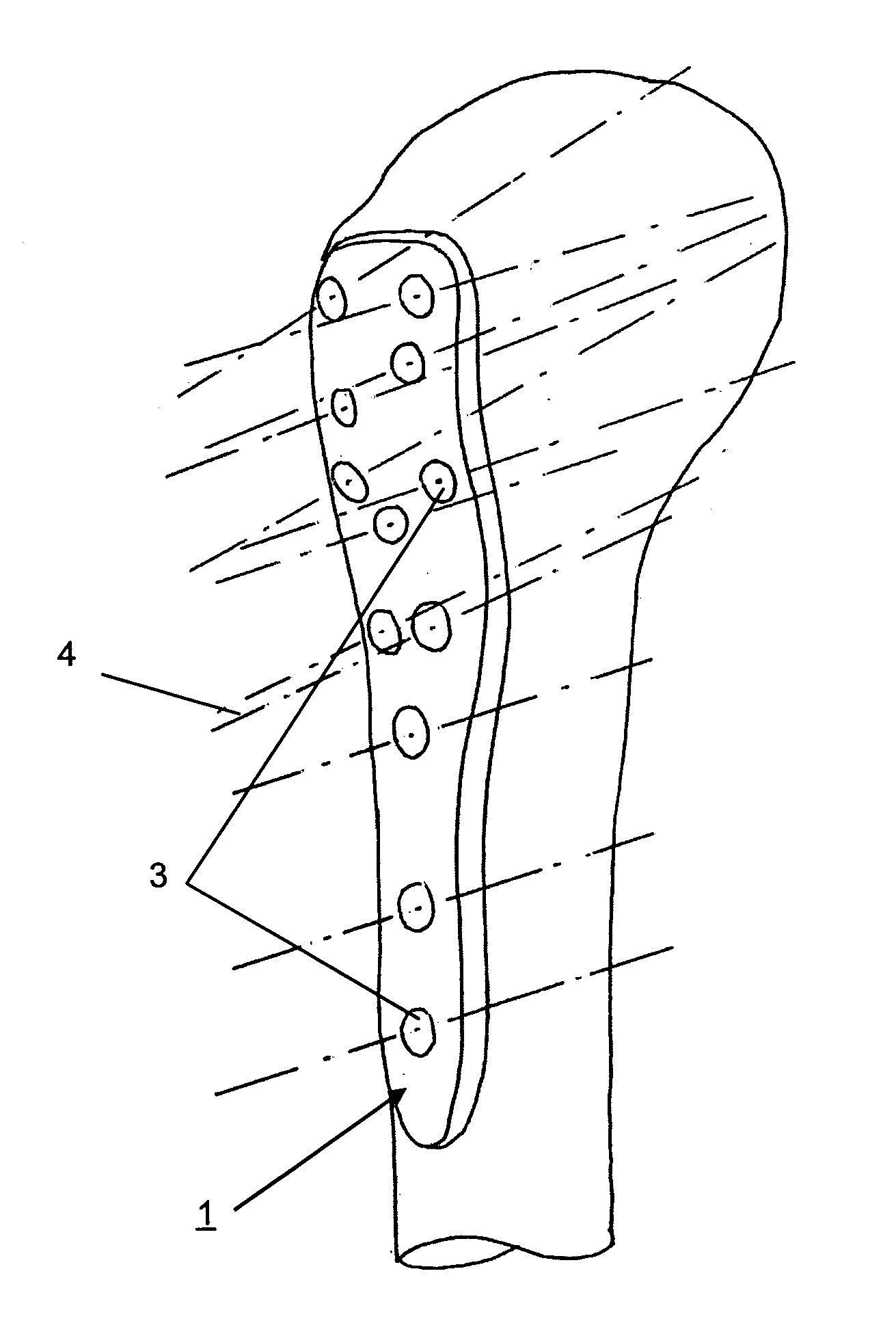
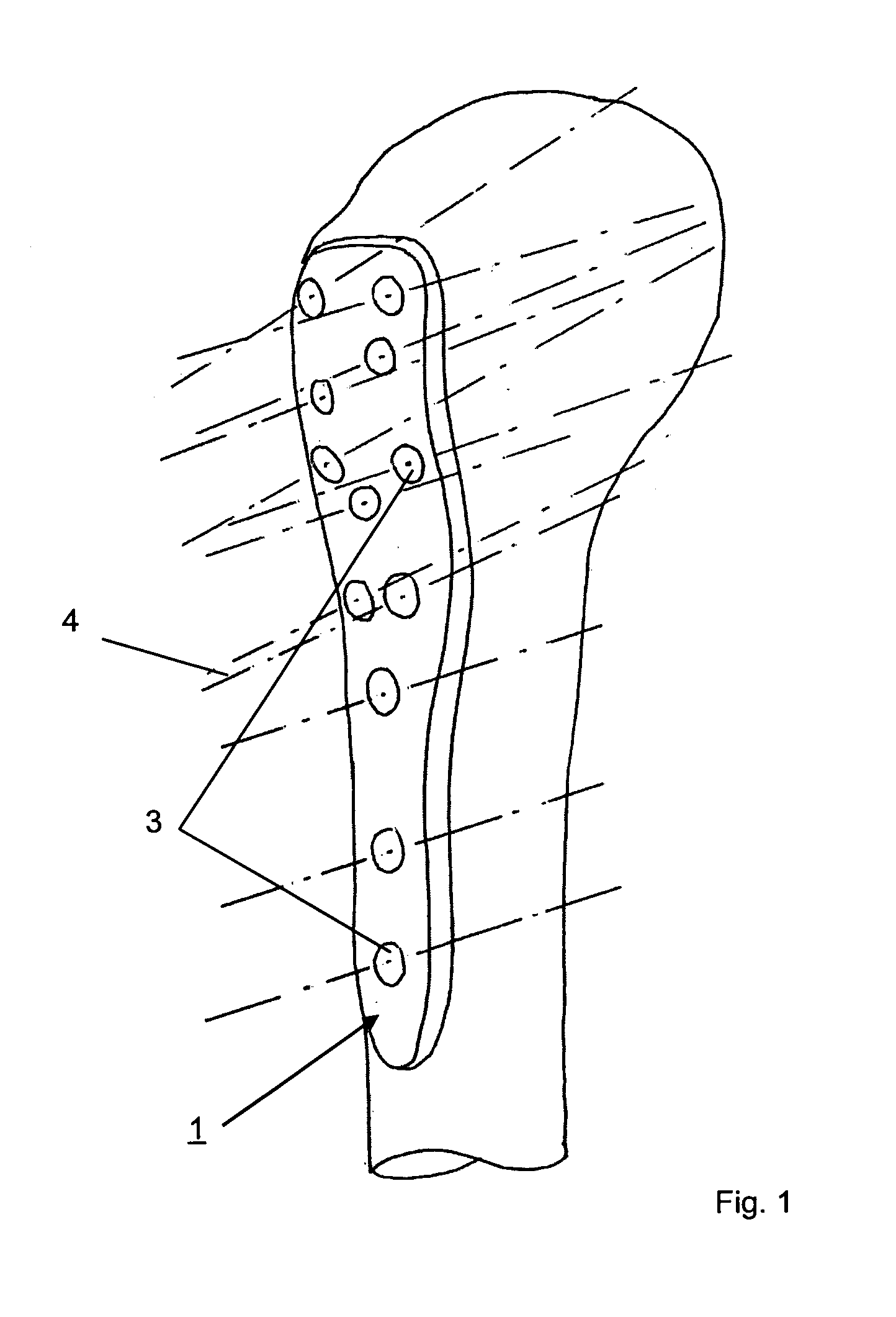
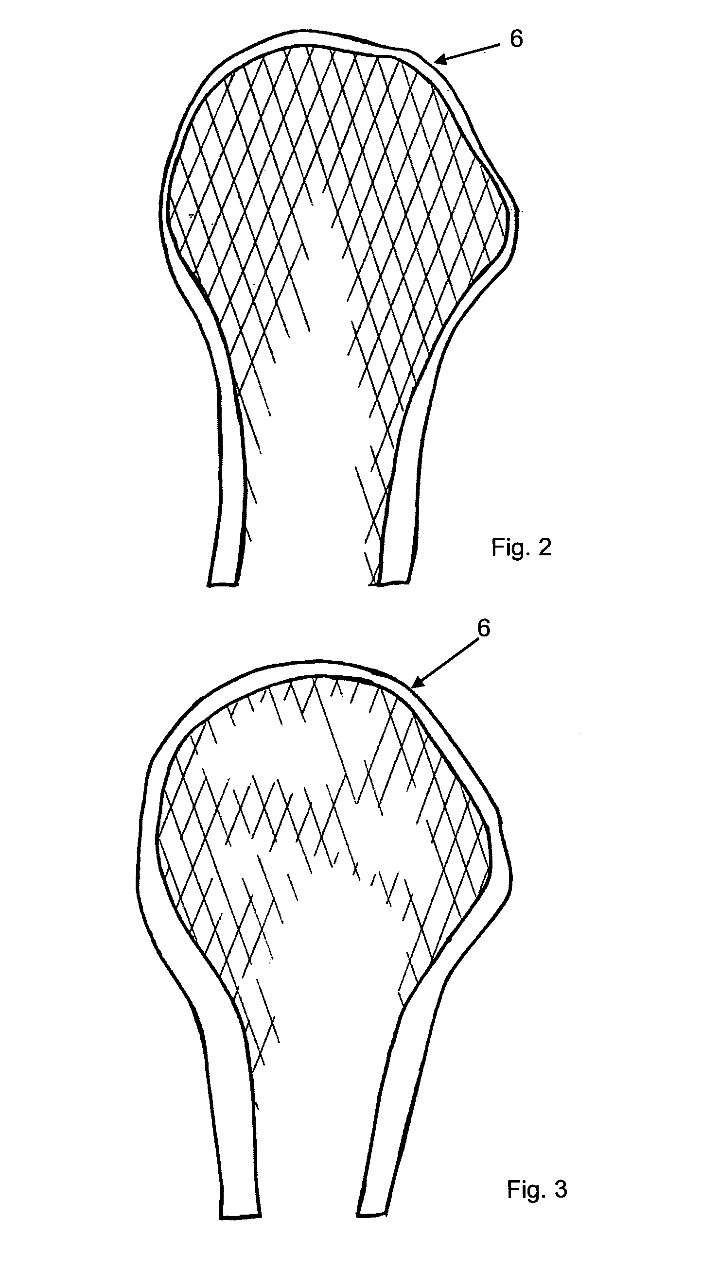
[0073]FIGS. 1 to 6 illustrate an embodiment of the method according to the invention applied on the proximal humerus 6. The most common surgical implant 1 used to treat proximal humeral fractures is a plate. According to the fracture classification, this surgical device is applied on a region of the humerus where the bone is still solid. Surgical accesses available for surgeons to position this implants 1 are limited by the proximal humerus anatomy: vessels, nerves, precious musculoskeletal structures limit the fixation of the surgical implant 1 in determined and well described regions of the humerus. Bone fixation elements 2, e.g. locking screws 2 are used both to fix that plate and to reduce the fracture fragments allowing fracture repair.

[0074]Nowadays medical devices companies design the plate geometry following the mean shape of the lateral portion of the humerus. Differently, the direction of the screws used to fix the fragment is based mostly on surgeon's suggestion or experi...


PUM


Abstract

A method for designing and / or optimizing an implant that has one or more through holes with a central axis for receiving a bone fixation element. The method includes: providing a general collection of three-dimensional bone quality data obtained from a patient population; identifying in the patient population N>2 categories of patients with significantly different N>2 homologous sub-collections of bone quality data; and designing an implant or optimizing an existing implant for each of the N>2 sub-collections such that the at least one through hole is located at an optimal place and with an optimal direction of the central axis relative to the implant. The optimal position and direction is chosen based on each of the N>2 sub-collections of data so as to obtain an optimal anchorage of the bone fixation element in the bone when introduced through the through hole.

Description

BACKGROUND OF THE INVENTION[0001]1. Field of the Invention[0002]The invention relates to a method for designing and / or optimizing a surgical device according to the preamble of claim 1, to a method for manufacturing a surgical device, in particular an implant according to the preamble of claim 7, to an implant manufactured by using said method according to the preamble of claim 8, and to a method for fixing bones using said implant according to the preamble of claim 19.[0003]2. Description of the Related Art[0004]Today surgical implants for fixation at or in a bone by means of bone fixation elements (e.g. screw or bolts) are manufactured taking into account the following parameters only[0005]a) anatomical shape of the bone to or in which the implant is to be fixed;[0006]b) type of fracture most frequently encountered; and[0007]c) size of the patient.[0008]No consideration is paid to the following parameters which are of even more importance than the above mentioned:[0009]d) quality ...

Claims


Application Information

Patent Timeline
IPC IPC(8): A61B17/80G06F17/50
CPCA61B17/1728A61B17/72A61B17/8052A61B17/8061A61B34/10A61B2034/108
Inventor BRIANZA, STEFANOSCHIUMA, DAMIANOTAMI, ANDREA
Owner AO TECH AG
Learn More