Brain cooling apparatus and brain cooling device suitable thereto

a brain and cooling device technology, applied in the direction of contraceptive devices, respirators, surgery, etc., can solve the problems of increasing the burden on the inner wall of the esophagus and the cuff itself, ischemic neuronal damage, and difficulty in holding the fluid level in the cuff at an appropriate level

Active Publication Date: 2012-12-20
UNIV OKAYAMA +1
View PDF4 Cites 11 Cited by
  • Summary
  • Abstract
  • Description
  • Claims
  • Application Information

AI Technical Summary

Benefits of technology

[0014]The present invention can provide a brain cooling apparatus that can circulate a fluid between the containing unit of a brain cooling device and

Problems solved by technology

It is known that this lack of oxygen supply destroys brain cells, that is, causes ischemic neuronal damage.
However even if the living body is resuscitated from the cardiac arrest state by these treatments, a mentioned ischemic neuronal damage may give a sequela to the brain.
In the case of the cooling device of Japanese Patent Application Laid-Open No. 2007-75505, the cuff must be closely contac

Method used


Image

  • Brain cooling apparatus and brain cooling device suitable thereto
  • Brain cooling apparatus and brain cooling device suitable thereto
  • Brain cooling apparatus and brain cooling device suitable thereto

Examples


Embodiment Construction

[0038]Embodiments of the present invention will now be described with reference to the accompanying drawings. The following embodiments are examples of carrying out the present invention, and not for limiting the technical scope of the present invention.

[0039]A preferred embodiment of the present invention will now be described with reference to the drawings.

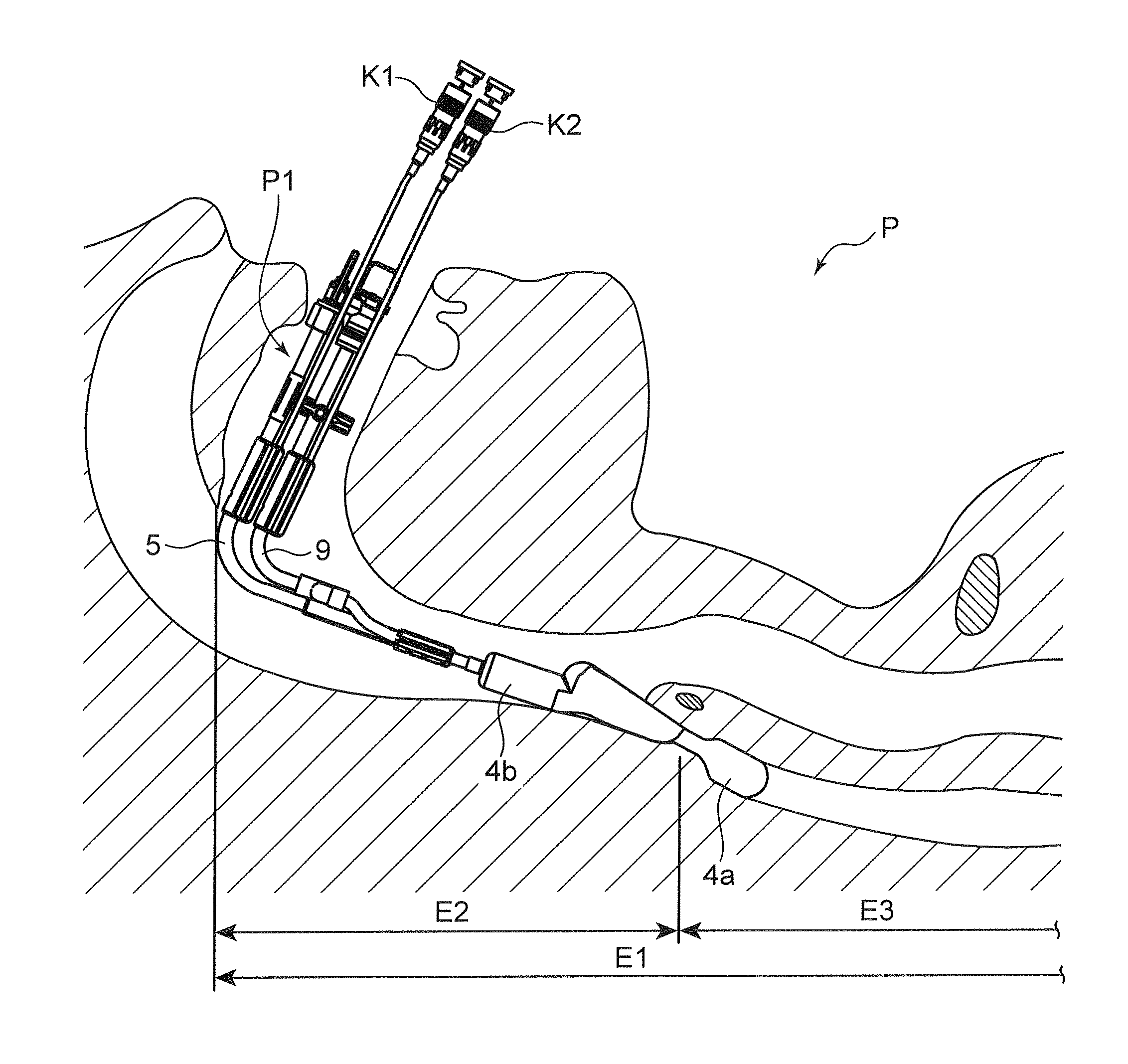
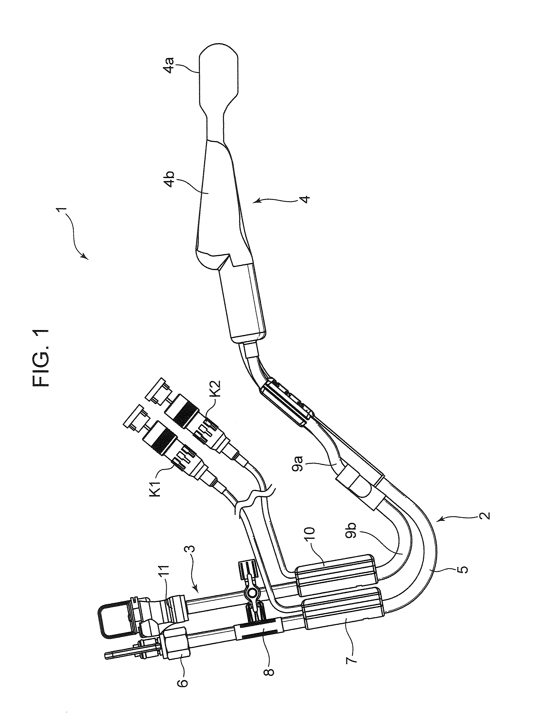
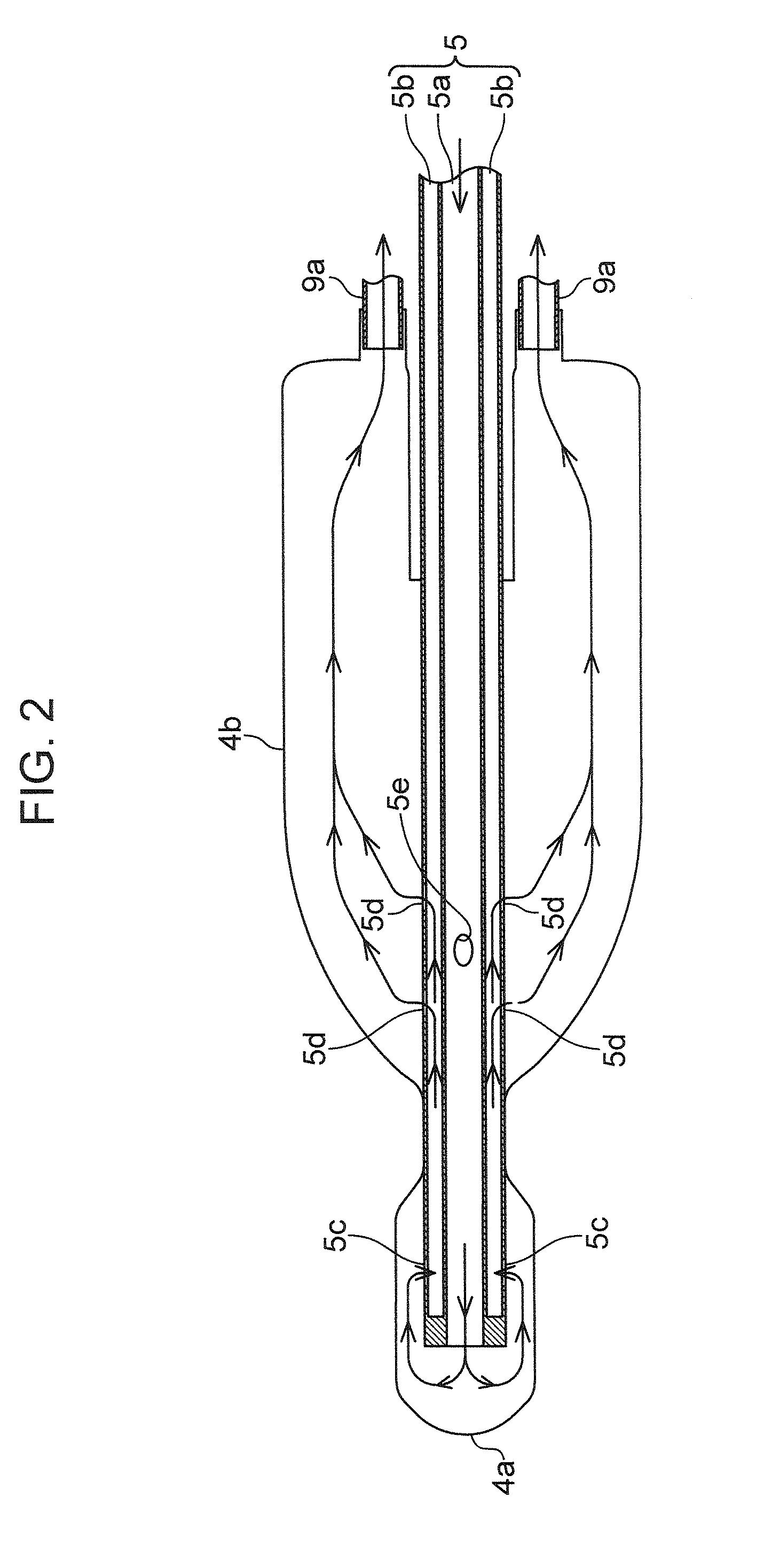
[0040]FIG. 1 is a side view depicting a general configuration of a brain cooling device according to an embodiment of the present invention. FIG. 2 is a schematic plan view depicting functions of the brain cooling device in FIG. 1. FIG. 3 is a schematic side view depicting a state of applying the brain cooling device in FIG. 1 to a patient.

[0041]As FIG. 1 to FIG. 3 illustrate, a brain cooling device 1 has a cuff 4 inside in which fluid can be contained, and an injection unit 2, and an ejection unit 3 which are connected to the cuff 4 respectively.

[0042]The cuff 4 has an elasticity which allows it to have a shrunk form when the f...


PUM


Abstract

A brain cooling apparatus is provided that can circulate a fluid between a containing unit of a brain cooling device and the brain cooling apparatus while maintaining an appropriate pressure of the fluid in the containing unit, and a brain cooling device suitable thereto also is provided. A control device circulates a physiological saline solution between a storage tank and a cuff by driving a first pump in a direction in which the physiological saline solution flows toward the cuff, and driving a second pump in a direction in which the physiological saline solution flows toward the storage tank. In this state, the control device adjusts the rotation speed of at least the second pump, so that the pressure of the physiological saline solution in the cuff becomes a preset target pressure.

Description

BACKGROUND OF THE INVENTION[0001]1. Field of the Invention[0002]The present invention relates to a device for cooing a brain of a living body.[0003]2. Description of the Background Art[0004]If a living body, including a human body, enters a state where the respiratory functions and the circulatory functions are incompetent, such as cardiac arrest (hereafter “cardiac arrest state”), oxygen supply to the brain becomes insufficient. It is known that this lack of oxygen supply destroys brain cells, that is, causes ischemic neuronal damage.[0005]Artificial respiration and other cardiac resuscitation treatments can be performed on a living body in the cardiac arrest state. However even if the living body is resuscitated from the cardiac arrest state by these treatments, a mentioned ischemic neuronal damage may give a sequela to the brain.[0006]With the foregoing in view, recently a so called “hypothermic therapy” is proposed as a treatment for preventing the ischemic neuronal damage from ...

Claims


Application Information

Patent Timeline
IPC IPC(8): A61F7/12
CPCA61F7/10A61M16/0459A61F2007/0056A61M16/04A61M16/0434A61M19/00A61M2205/3606A61M16/0409A61M16/0438A61F7/0085A61F2007/0002A61F2007/0092A61B2090/065A61M2016/0027A61M16/0445A61F7/123
Inventor TAKEDA, YOSHIMASAMORITA, KIYOSHIHASHIMOTO, HIROSHITSUJI, HIDEKAZUKOKUBU, MASATOMO
Owner UNIV OKAYAMA
Why Eureka
Try Eureka