
Footwear Pressure Elimination & Dipersibility Systematic

a technology of footwear and pressure elimination, applied in footwear, heels, top-pieces, etc., can solve the problems of inefficient, unfavorable, and inefficient, and achieve the effect of enhancing the inside cushioning sole, reducing the friction between the foot and the shoe, and reducing the friction between the shoe and the sho

Inactive Publication Date: 2012-12-27
TANG HUNG V
View PDF9 Cites 22 Cited by
  • Summary
  • Abstract
  • Description
  • Claims
  • Application Information

AI Technical Summary

Benefits of technology

[0005]Unlike prior arts invented adaptable cushion to place inside the footwear and joints loose beneath of the foot. This present invention capable to provides greater engagement to footwear and helps recessing kinetic friction between the foot and footwear. Mean of advantage feature to invent a sole permanently insert to inside the footwear. Said it is manufacture and installation in place of time. This invention is the concept of clutching cushiony sole into footwear as an interior embodiment element to providing stabilization. Said it is models capable to enhanced inside cushiony sole or extend c

Problems solved by technology

The solution stated causes of poor impacts in result to damage the structure of plantar fascia ligament.
Such as Trauma is a result of forces impact or others as poor biomechanical alignment may lead to foot pain as well as other typical occur in muscle strains, bruises, sprain and fractures.
Other prior inventions have similar conception to extended cushion or invented adaptable insole, however those arts seen not favorable preferred to inefficient embodiment as foot wears expectation.
Other prior arts consists thickness appearance which might not favorable to some types of fashion.
Therefore others invented in less thickness models however in matter of fact that consisting lack of cushion capable to shocks absorbing.
Mean its lack of cushiony to absorbing impact from outsider's shocks which is that causes strain to the foot and fatigues to lower legs when the feet strike on the ground's surface.

Method used


Image

  • Footwear Pressure Elimination & Dipersibility Systematic
  • Footwear Pressure Elimination & Dipersibility Systematic

Examples


Embodiment Construction

of Assembly Manufacture Installation

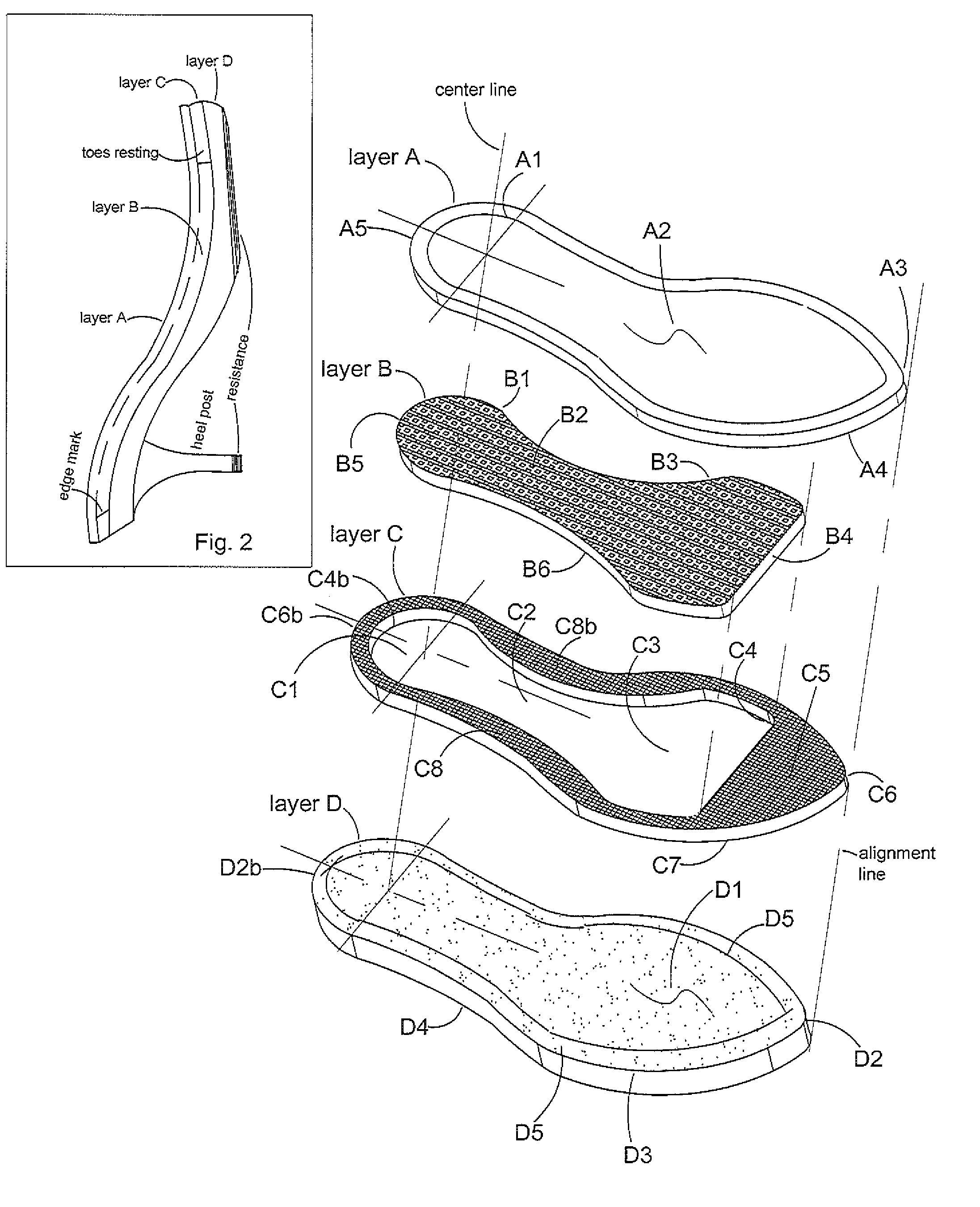
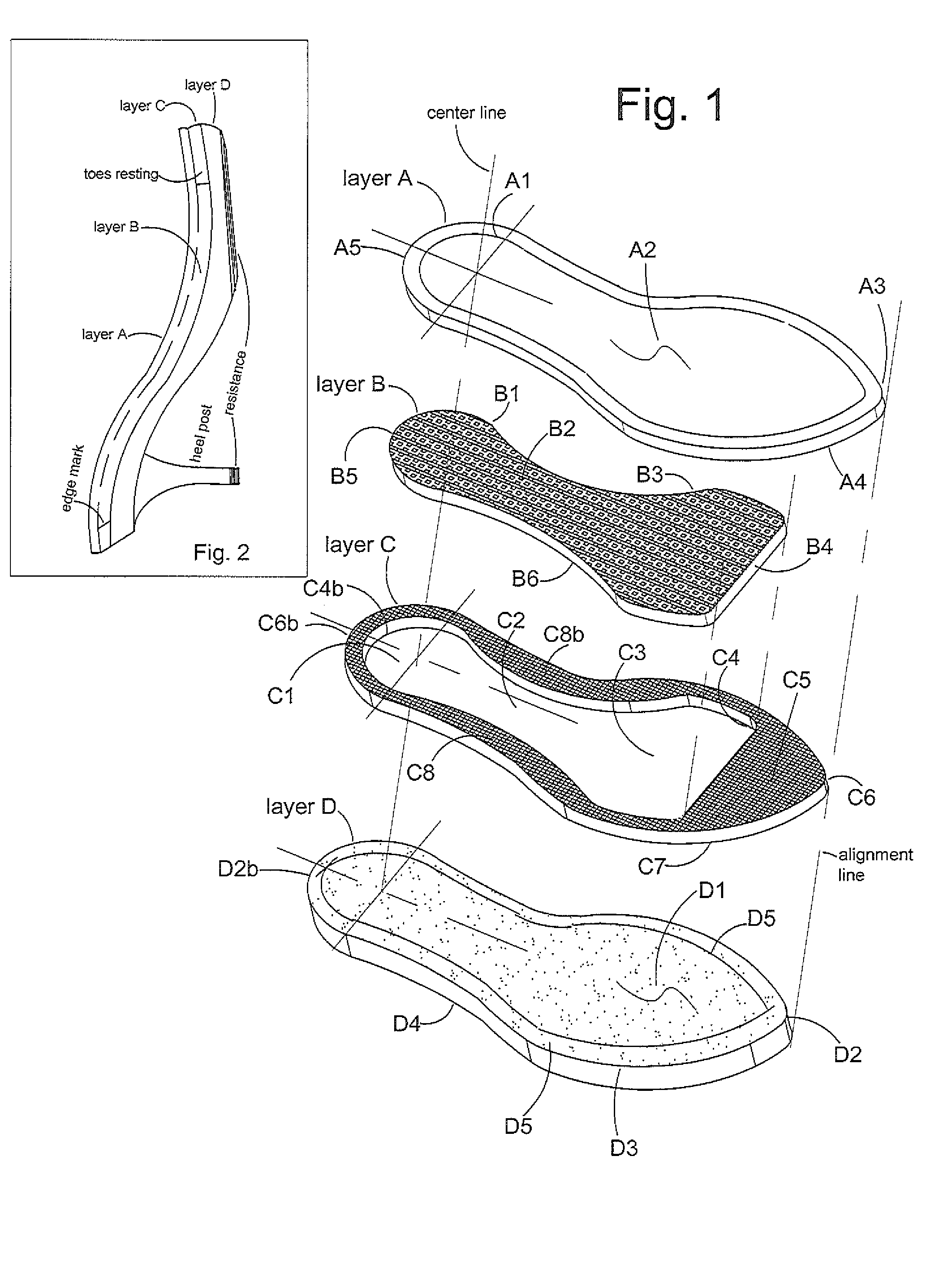
[0011]Layer D is the outer layer consisting in alignment with above layers C, B and A as preferred an embodiment composition. Preference to assembly layer C on to top layer D as FIG. 1 show. Pref. layer D1 surface solid and firmness capable to be adhesive by placing pref. C7 surface onto pref. D1 surface consisting alignment edge to edge evenly preferred C4 inner edge inline pref. D5 inner mark. Said technical adhesive onto top pref. D5 surface in parallel flat and evenly from edge to edge pref. D2 outer alignment against pref. C6 outer edge comprising pref. D2b outer edge in heel in vertically flat to C6b outer edge in heel. Pref. B layer position inside cutout channel pref. C1 heel, C2 arch and C3 forefoot in parallel with the ground's surface. Alignment pref. B5 outer edge insert to inside pref. C4b inner edge consisting pref. B4 forefoot outer edge insert to inside pref. C4 inner edge.

[0012]The top layer A assembly on to below layers and it co...


PUM


Abstract

Pain caused by plantar fasciitis is usually accompanied by heel pain and arch pain or forefoot regions are possibly most painful when you first attempt to stand or walk. There are also many other painful conditions of the feet that could be cause from the foot discomfort in footwear composition or technical designed. The present invention is footwear consisting composition method to disperse an exertion of force such as pressures recess of the foot relating above painful conditions. Said it mean of relieving foot strain in the advantage of composition interior cushiony sole that it insert to inside of an outer element composed in corresponding cushiony sole of others in advantage of pain reliever or shocks absorption. FIG. 2 preferred an embodiment to accomplish of present invention. Top layer A preferred to top fine adhered above Pref. C layer cast wherein cauterized in midsection pref. B inside sole series attachment construct outer layer pref. D consisting resistance outer impact.

Description

CROSS REFERENCE TO RELATED APPLICATION[0001]This application is improvement and update continuation of Ser. No. 13 / 165,434 filed on Aug. 22, 2011.THE INVENTION BACKGROUND[0002]The field of present invention is related to enhance comfort footwear to be composed into a universal model and fashion. This invention related mid-sole shocks absorption mean of capable to an exertion of force relief or pressure recesses. The concept of this invention is contour to providing maximum shock absorbing in preferred painful condition developed or relates to plantar fasciitis plus comprising an advance feature to conceal the vertical dimension appearance subject to minimum thickness footwear. This invention technically is an interior sole interaction of elastomeric materials embodiment, comprising capable to compression to de-compress essentially an oblong regions preferred extending transversely to an axis of the foot. Mean it recess pressure to elongate in a direction generally to an axis of the ...

Claims


Application Information

Patent Timeline
IPC IPC(8): A43B13/18
CPCA43B13/12A43B13/187A43B7/144A43B21/00A43B7/148A43B13/16A43B7/1445
Inventor TANG, HUNG V.
Owner TANG HUNG V
Learn More