Electric booster and brake device using the same

a technology of brake device and electric booster, which is applied in the direction of brake system, fluid coupling, instruments, etc., can solve the problems of difficult to obtain favorable braking feeling, and achieve the effect of reducing the number of structural components, reducing the torque resistance of the gear power transmission mechanism, and facilitating the reverse rotation of the rotor

Inactive Publication Date: 2012-12-27
BOSCH CORP
View PDF4 Cites 11 Cited by
  • Summary
  • Abstract
  • Description
  • Claims
  • Application Information

AI Technical Summary

Benefits of technology

[0014]As a result of configuring the electric booster of the invention in the manner described above, rotation of the electric motor causes the impelling force to be applied to the power piston, whereby the power piston is actuated. The output, which is boosted at the predetermined servo ratio from the input resulting from the actuation of the power piston, is generated through the output shaft. In addition, the reaction force that accompanies the output is transmitted from the output shaft to the reaction force member that is formed from the viscoelastic material. Moreover, the input receiving member that receives the input is separated by the predetermined gap from the reaction force member at non-actuated times, and abuts against the reaction force member at actuated times due to application of the predetermined input. As a result, it is possible to realize an electric booster that can mechanically exhibit both a jump-in characteristic resulting from the predetermined gap between the input receiving member and the reaction force member and the hysteresis characteristic resulting from the viscoelastic properties of the reaction force member, without relying on control software.
[0015]In addition, rotation of the rotor of the electric motor causes the impelling force that is directly applied to the power piston. Accordingly, a gear power transmission mechanism like that in the electric booster disclosed in JP-A-2008-81033 does not need to be used, and thus the number of structural components can be reduced. This makes it possible to make the electric booster smaller to this extent. Moreover, as a result of not using the gear power transmission mechanism, when there is reverse rotation of the rotor when the power piston retracts in a full load region of the electric booster, torque resistance resulting from the gear power transmission mechanism is reduced, and the reverse rotation of the rotor can take place more smoothly.
[0016]In addition, the relative displacement of the input receiving member and the power piston support member that supports the power piston is detected by the relative displacement detection means, and the electric motor actuates the power piston based on the previously described relative displacement detected by the relative displacement detection means. As a result, the relative displacement detection means can be provided integrally inside the electric booster. Thus, it is possible to reduce the number of structural components, and it is also unnecessary to specially provide space for installing the relative displacement detection means outside of the electric booster. Accordingly, it is possible to make the installation space for the electric booster even smaller, thus meaning that there is greater design freedom in terms of installing the electric booster. In addition, the actuation of the electric motor is controlled based on the relative displacement of the power piston support member and the input receiving member that is detected by the relative displacement detection means. Thus, the actuation of electric booster can be controlled with higher accuracy.
[0017]In this case, as a result of the relative displacement detection means having the magnet that is disposed in the input receiving member and the magnetic sensor that is disposed in the power piston support member and that generates an output based on the magnetic field of the magnet, the configuration of the relative displacement detection means can be made simpler.
[0018]Moreover, as a result of providing the reaction disc formed of rubber as the reaction force member, the configuration of the reaction force member can be made even simpler.
[0019]Moreover, the brake device including the electric booster of the invention utilizes the electric booster of the invention and thus the installation space for the brake device can be made even smaller, thus meaning that there is greater design freedom in terms of installing the brake device. Moreover, brake control can be performed with higher accuracy.

Problems solved by technology

Thus, it faces the problem that a favorable braking feeling is hard to obtain.

Method used


Image

  • Electric booster and brake device using the same
  • Electric booster and brake device using the same
  • Electric booster and brake device using the same

Examples


Embodiment Construction

[0023]Hereinafter a mode for carrying out the invention will be explained with reference to the drawings.

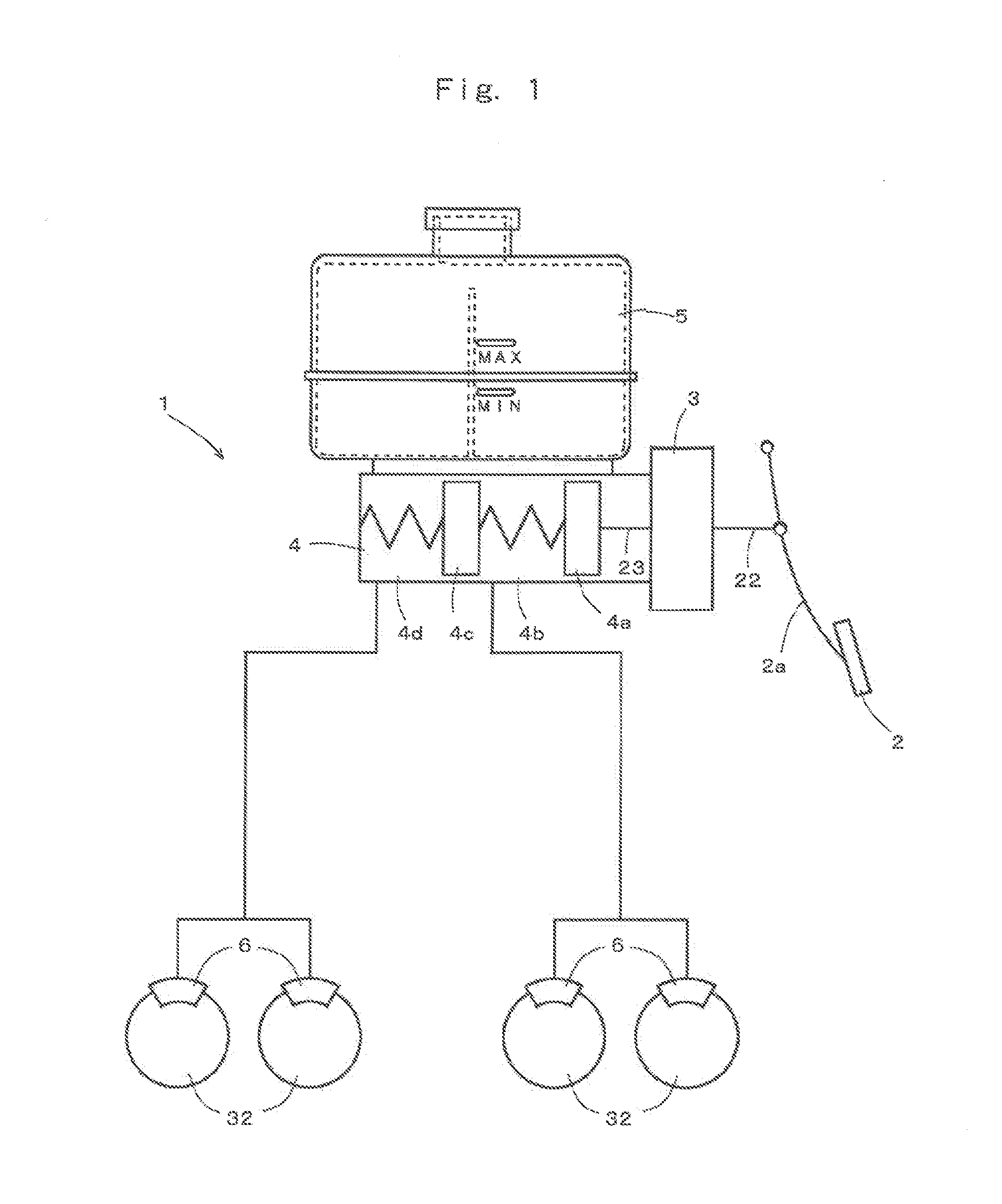
[0024]FIG. 1 is a schematic view of a brake device provided with one example embodiment of an electric booster according to the invention.

[0025]As shown in FIG. 1, an example brake device 1 is fundamentally the same as a generally known dual line brake device. More specifically, the brake device 1 is provided with a brake pedal 2, an electric booster 3, a tandem master cylinder 4, a reservoir tank 5, and brake cylinders 6.

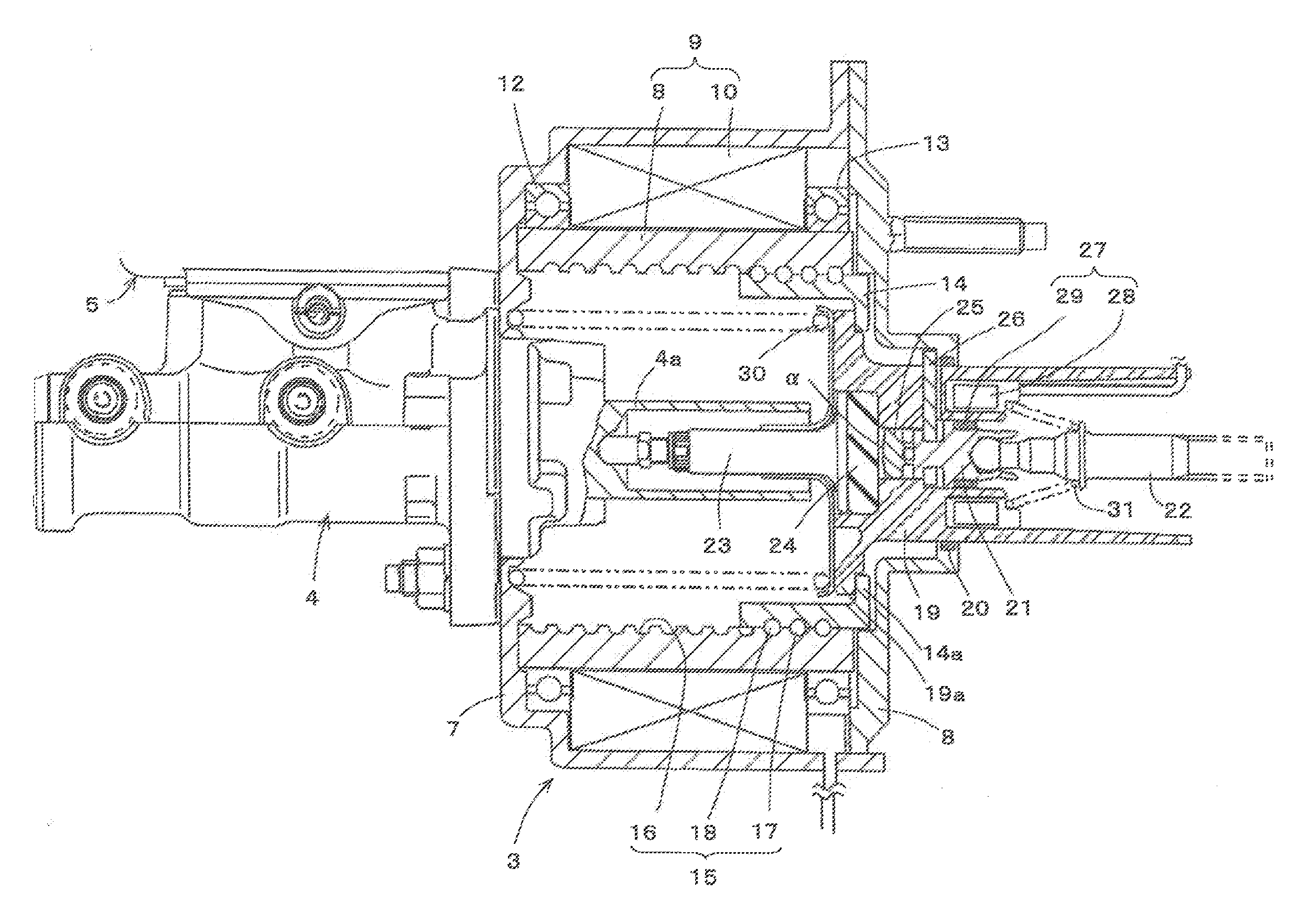
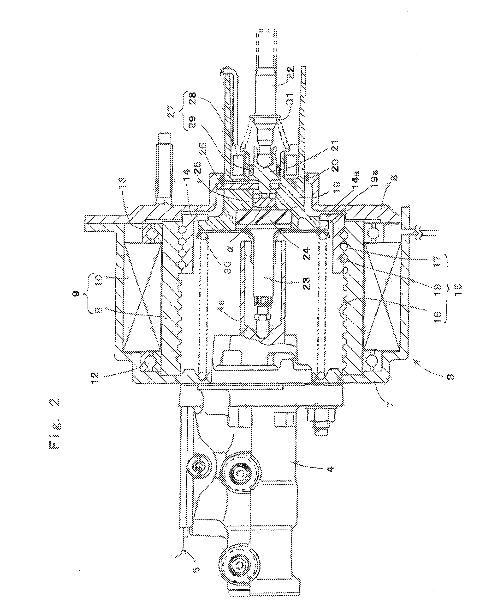
[0026]As shown in FIG. 2, the example electric booster 3 has a front housing 7 and a rear housing 8 that are connected to each other. An electric motor 9 is disposed within the front housing 7. This electric motor 9 includes: a stator 10 that is an annular, magnetic force generating member formed from a coil that is fixed to and supported by the front housing 7; and a rotor 11 that is a cylindrical, rotating member that is disposed at an inner periphery of the s...


PUM


Abstract

[Problem] To provide an electric booster that can mechanically exhibit a jump-in characteristic and hysteresis characteristic without relying on control software.
[Means for Resolution] An electric booster 3 includes an electric motor 9; a power piston 14 that receives impelling force generated by rotation of the electric motor 9; a power piston support member 19 that supports the power piston 14; an input shaft 22; an input receiving member 21 that receives input from the input shaft 22 and that is provided so as to be relatively moveable with respect to the power piston support member 19; an output shaft 23; reaction disc 24, formed from a viscoelastic material, that receives reaction force from the output shaft 23; and a spacing member 25 that is connected to the input receiving member 21 and that is disposed with a predetermined gap α between it and the reaction disc 24.

Description

[0001]The present invention relates to the technical field of electric boosters that generate an output by boosting an input at a predetermined servo ratio using electric power, and to the technical field of brake devices that use the electric boosters.BACKGROUND OF THE INVENTION[0002]In known brake devices for automobiles such as passenger vehicles, a brake booster is used that generates an output by boosting an input at a predetermined servo ratio using electric power. This brake booster generates an output by boosting an input that is based on a pedal depression force. Then, the output of the brake booster actuates a master cylinder, thus allowing a large brake force to be obtained using a small pedal depression force.[0003]As an example of this known brake booster, an electric booster is proposed that uses electric power (for example, refer to JP-A-2008-81033). In the electric booster disclosed in JP-A-2008-81033, when a brake pedal is depressed, an electric motor is driven and ...

Claims


Application Information

Patent Timeline
Patent Type & Authority Applications(United States)
IPC IPC(8): B60T13/74G01B7/00
CPCG01D5/145B60T13/745
Inventor MORI, YASUSHI
Owner BOSCH CORP
Why Eureka
Try Eureka