Dual-loop cooling system

Inactive Publication Date: 2012-12-27
WISCONSIN ALUMNI RES FOUND
View PDF8 Cites 51 Cited by
  • Summary
  • Abstract
  • Description
  • Claims
  • Application Information

AI Technical Summary

Benefits of technology

[0023]The system described herein minimizes circulating oil through the chamber by providing circulation routes that bypass the chamber, adjusts to w

Problems solved by technology

Maintaining such a temperature range is a challenging problem that is only increasing in importance and difficulty as semiconductor technology continues to progress.
However, these systems are inherently limited in terms of their performance and efficiency.
Due to the very low volumetric heat capacity of air, a large volume of air flow is required to remove the heat load of even one processor.
Furthermore, air-cooled systems are not only inefficient in themselves but also cause the electronics they cool to operate less efficiently.
However, the intervening materials between the water and the work piece induce significant thermal resistance, which reduces the efficiency of the system.
In addition to the thermal resistance, the intervening materials add to the cost and time of manufacture, constitute additional points of failure, and provide possible disposal issues.
Finally, the intervening materials render the system unable to efficiently deal with local hot spots on a work piece.
However, the dielectric coolants are less efficient coolants than water.
However, spray cooling is limited by several factors.
First, spray cooling requires a significant working volume to enable the atomi

Method used


Image

  • Dual-loop cooling system
  • Dual-loop cooling system
  • Dual-loop cooling system

Examples


Embodiment Construction

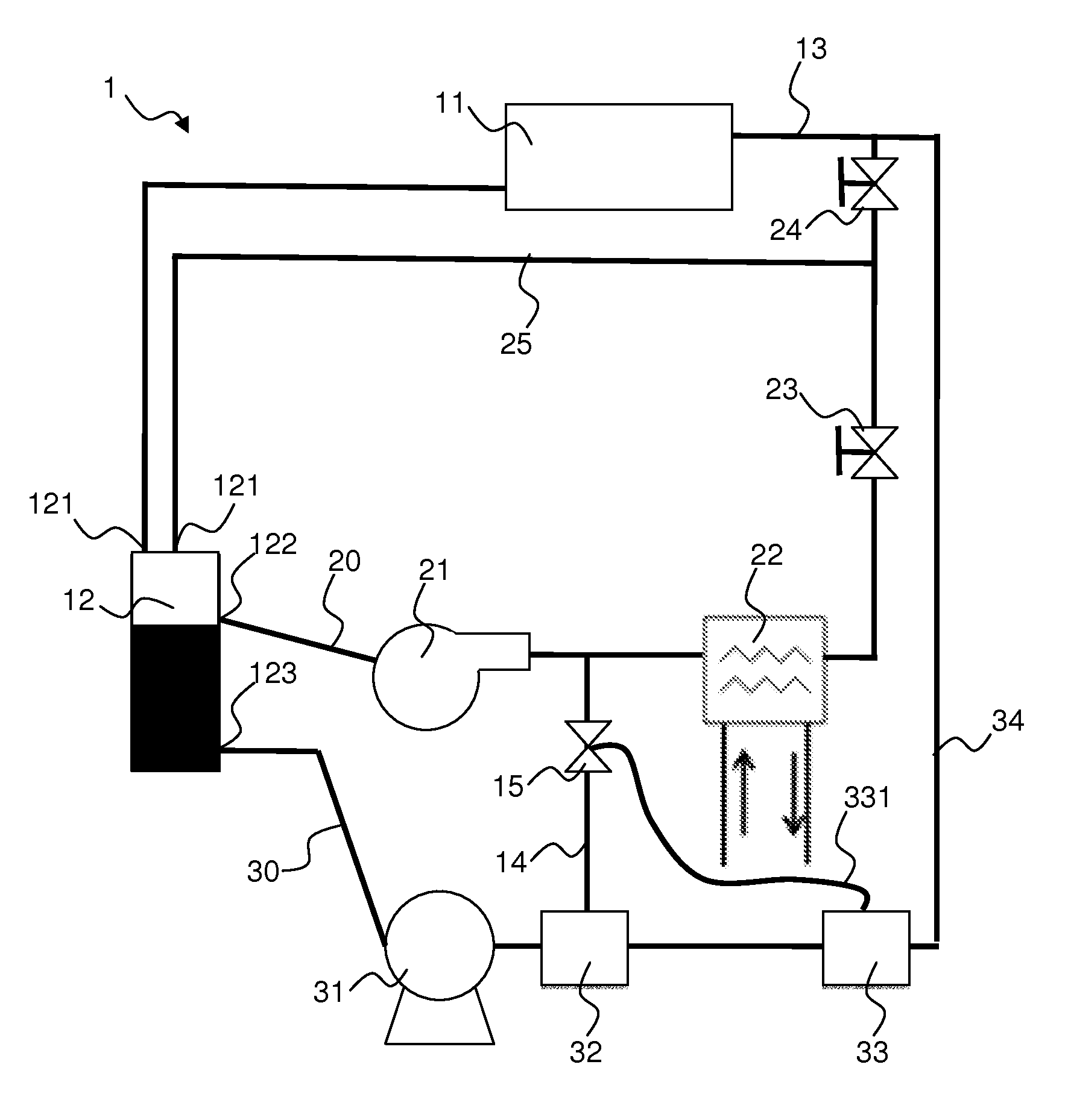
[0032]One aspect of the present invention involves cooling a surface in a chamber with a liquid coolant wherein the coolant at least partially undergoes a phase change to a vapor (i.e., evaporates) upon entering the chamber and prior to contacting the surface. This is achieved by preparing coolant to be introduced in the chamber at or approximately at the coolant's saturation condition.

[0033]The general term “coolant” refers to any fluid capable of undergoing a phase change from liquid to vapor or vice versa at or near the operating temperatures and pressures of an apparatus as described herein. The term refers herein to the fluid in the liquid phase, the vapor phase, and mixtures thereof. A number of coolants may be selected for use within the apparatus described herein depending on cost and level of optimization desired. Non-limiting examples include water, HFE-7000, R-245fa, FC-72, and FC-40. Other coolants are known in the art. Water is readily abundant and inexpensive. However,...


PUM


Abstract

Disclosed are methods and apparatuses for cooling a work piece surface using a dual-loop cooling system. The system includes a vapor-compression loop and a liquid-evaporation loop. The loops are configured to prepare a coolant at or approximately at saturation for delivery into a chamber for cooling the surface. A preferred liquid-evaporation loop includes a chamber, a phase separator, a liquid pressurizer, and a vapor mixer that heats the coolant to or near its saturation temperature. A preferred vapor-compression loop includes the phase separator, a compressor, a condenser, an expansion valve, and a return line. The vapor mixer preferably heats the coolant by mixing liquid coolant with vapor coolant derived from the vapor-compression loop. A two-phase flow detector may be disposed downstream of the vapor mixer and be in communication with a vapor valve disposed upstream of the vapor mixer to ensure that an appropriate amount of vapor is fed into the vapor mixer to induce evaporation. Methods include cooling a surface by cycling a coolant through the liquid-evaporation loop and preparing the coolant at saturation with vapor derived from the vapor-compression loop.

Description

FIELD OF THE INVENTION[0001]The present invention is directed to methods and apparatuses for cooling work pieces such as processors or other electronic devices.BACKGROUND[0002]Methods for maintaining electronic devices within a safe and desirable operating temperature range have been a topic of research since the invention of the transistor. Maintaining such a temperature range is a challenging problem that is only increasing in importance and difficulty as semiconductor technology continues to progress. State of the art microprocessors easily produce more than 40 W of thermal energy per square centimeter of the microchip surface. Power electronics can attain heat densities three times this level.[0003]In addition to the requirement to manage such high heat intensity, there is a need to remove the thermal energy efficiently, both in terms of energy expended and space required. According to the Department of Energy, approximately 3% of electricity used in the United States is devoted...

Claims


Application Information

Patent Timeline
IPC IPC(8): F25D31/00F25D25/00
CPCF25B25/00F25B41/00F25B2400/0409F25B2400/0401F25B2400/0403F25B41/04F25B23/006F28D15/0266F25B41/20H01L23/427H01L23/4735H01L2924/0002H01L2924/00
Inventor SHEDD, TIMOTHY A.
Owner WISCONSIN ALUMNI RES FOUND
Why Eureka
Try Eureka